A continuous calcination system and method for pearlescent materials

A pearlescent material and calcination technology, which is applied in the direction of chemical instruments and methods, fibrous fillers, inorganic pigment treatment, etc., can solve the unstable quality control of pearlescent material calcination, unfavorable calcining of pearlescent material with small batch color number, and affect the quality of pearlescent material products and other problems, to achieve good calcination effect, realize energy consumption calcination, and shorten calcination time

Active Publication Date: 2021-10-19
INST OF PROCESS ENG CHINESE ACAD OF SCI +1
View PDF4 Cites 0 Cited by
  • Summary
  • Abstract
  • Description
  • Claims
  • Application Information

AI Technical Summary

Problems solved by technology

[0004] The traditional calcination device for pearlescent material production is a roller kiln. The pearlescent material is sent to the heating furnace for calcination through the conveyor belt. The surface of the body can be completely reacted, but it is difficult to realize the full reaction of the powder inside the piled powder. This calcination method is very unstable and inefficient for the quality control of the pearlescent material calcination, which affects the product quality of the pearlescent material.
In addition, in order to prevent the powder from taking away heat, the moving speed of the conveyor belt must be reduced. Generally, the calcining time of pearlescent materials is as long as several hours, which greatly increases the power consumption and directly increases the calcining cost.
Thirdly, due to the low heat transfer efficiency, the volume of roller kiln equipment is often large and inconvenient to clean, which is not conducive to the calcination of small batches of color number pearlescent materials

Method used


Image

  • A continuous calcination system and method for pearlescent materials

Examples


Embodiment 1

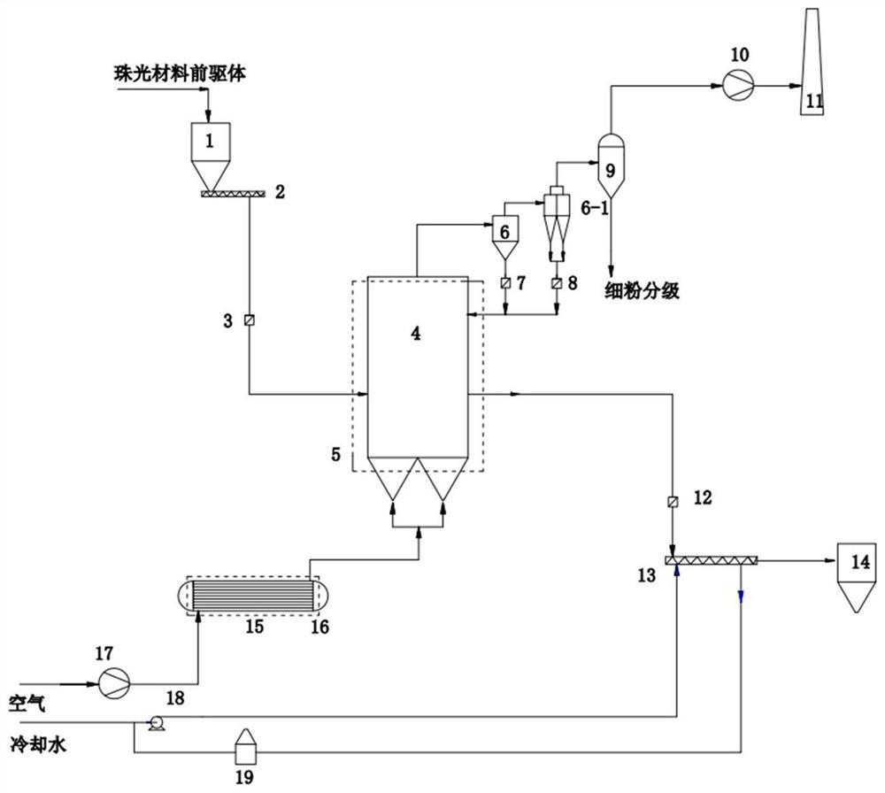
[0031] Such as figure 1 As shown, a system for the continuous calcination process of pearlescent materials, the system includes a raw material bin 1 connected in sequence, a screw feeder 2, a feed valve 3, a fluidized bed reactor 4, a main heating furnace 5, and a primary cyclone separation Device 6, secondary cyclone separator 6-1, one-point return valve 7, two-point return valve 8, metal dust collector 9, induced draft fan 10, chimney 11, discharge valve 12, water-cooled screw 13, product silo 14 , gas heat exchanger 15, gas heating electric furnace 16, air blower 17, water pump 18 and cooling tower 19;

[0032]In the system, the outlet of the raw material bin 1 is connected to the screw feeder 2, the outlet of the screw feeder 2 is connected to the inlet of the feed valve 3, and the outlet of the feed valve 3 is connected to the fluidized bed The feed port of the reactor 4 is connected, the gas inlet of the fluidized bed reactor 4 is connected with the gas outlet of the ga...

Embodiment 2

[0036] A method for continuous calcination of pearlescent materials based on the system described in Example 1, the method for continuous calcination of pearlescent materials comprises the following steps:

[0037] 1) The pearlescent material precursor powder enters the fluidized bed reactor 4 through the raw material bin 1 through the screw feeder 2 through the feed valve 3; Coarse particles, after being collected by the primary cyclone separator 6 and the secondary cyclone separator 6-1, enter the fluidized bed reactor 4 through the one-point return valve 7 and the two-point return valve 8; the two-stage cyclone separator 6- 1. The finer particle powder entrained in the discharged high-temperature flue gas is collected by the high-temperature metal dust collector 9 and then stored. The purified high-temperature dust-containing gas passes through the induced draft fan 10 and is discharged from the chimney 11; the fully calcined pearlescent material Discharge from the outlet o...

Embodiment 3

[0043] Using the method described in Example 2, the silver-white series pearlescent material precursor powder with a water content of 5% enters the fluidized bed reactor 4 through the feed valve 3 through the raw material bin 1 through the screw feeder 2; the air is heated by the gas The gas heat exchanger 15 heated by the electric furnace 16 enters the fluidized bed reactor 4 to fluidize and calcine the pearlescent material precursor powder in the fluidized bed reactor 4, the calcination temperature is 550° C., and the calcination time is 60 minutes; The first-stage cyclone separator 6 and the second-stage cyclone separator 6-1 enter the metal dust collector 9 for purification, and the purified low-temperature flue gas passes through the induced draft fan 10 and is discharged from the chimney 11; the cooling water of the process water main pipe is pressurized by the water pump 18 , into the water inlet of the water-cooled screw 13 to exchange heat with the hot material, and th...


PUM


Abstract

The invention relates to the production field of pearlescent materials, in particular to a continuous calcination system and method for pearlescent materials. The fluidized continuous calcination technology is used to perform calcination heat treatment on the pearlescent material precursor produced in the coating section to produce pearlescent materials. The present invention simplifies the calcination process by means of an electric heating fluidized bed, improves calcination efficiency, reduces calcination energy consumption, and at the same time greatly reduces the area occupied by the equipment, reduces the vertical height of the equipment, and can meet the annual output of special pearlescent materials lower than 100 tons production. The invention has the advantages of miniaturized equipment volume, short process, high continuous production efficiency, good calcination effect, low production energy consumption, etc., is suitable for the industrial calcination process section of coated titanium mica pearlescent materials, and has good economic and social benefits.

Description

technical field [0001] The invention belongs to the fields of pearlescent materials and chemical industry, and in particular relates to a system and method for a continuous calcination process of pearlescent materials. Background technique [0002] Pearlescent materials can show a soft, eye-catching, colorful pearlescent effect through the action of light, and are widely used in coatings, inks, cosmetics, plastics, rubber and printing industries. Mica titanium pearlescent material is one of the most representative ones. It is formed by coating one or more layers of titanium or other metal oxides on the surface of the sheet-like substrate through a chemical coating process with a sheet-like mica substrate as the core. Micronized. [0003] Calcination heat treatment of pearlescent material precursor is an important process step in the production of mica titanium pearlescent pigments. The pearlescent material produced by the existing liquid phase process, after the coating pr...

Claims


Application Information

Patent Timeline
Patent Type & Authority Patents(China)
IPC IPC(8): C09C1/00C09C3/04C09C3/06
CPCC09C1/0021C09C3/006C09C3/043C09C3/063C09C2200/102
Inventor 吕鹏鹏吴昌梓朱庆山邵国强吴昌锦吴昌在吴万里吴昊吴俊吴万琛
Owner INST OF PROCESS ENG CHINESE ACAD OF SCI
Why Eureka
Try Eureka