Heat treatment device for conveying machine part machining

A technology for heat treatment devices and conveying machinery, applied in heat treatment furnaces, heat treatment equipment, metal processing equipment, etc., can solve problems such as easy to be scalded, low efficiency, easy to scald staff, etc., to enhance safety, improve practicability, reduce The effect of labor intensity

Active Publication Date: 2020-11-10
泰安市鲁阳金属制品有限公司
View PDF4 Cites 2 Cited by
  • Summary
  • Abstract
  • Description
  • Claims
  • Application Information

AI Technical Summary

Problems solved by technology

[0003] The existing processing and heat treatment methods for small parts of conveying machinery are usually manually heated by hand, such as pipes. Manual heating is very dangerous, and it is easy to be scalded if you are not careful, and the efficiency is low, and it is harmful to heated pipes. Put directly into the water to cool down, the huge difference in temperature is easy to splash the evaporated water mist, and it is easy to burn the staff

Method used


Image

  • Heat treatment device for conveying machine part machining
  • Heat treatment device for conveying machine part machining
  • Heat treatment device for conveying machine part machining

Examples


Embodiment Construction

[0028] The following will clearly and completely describe the technical solutions in the embodiments of the present invention with reference to the accompanying drawings in the embodiments of the present invention. Obviously, the described embodiments are only some, not all, embodiments of the present invention. Based on the embodiments of the present invention, all other embodiments obtained by persons of ordinary skill in the art without making creative efforts belong to the protection scope of the present invention.

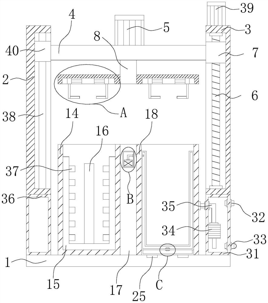
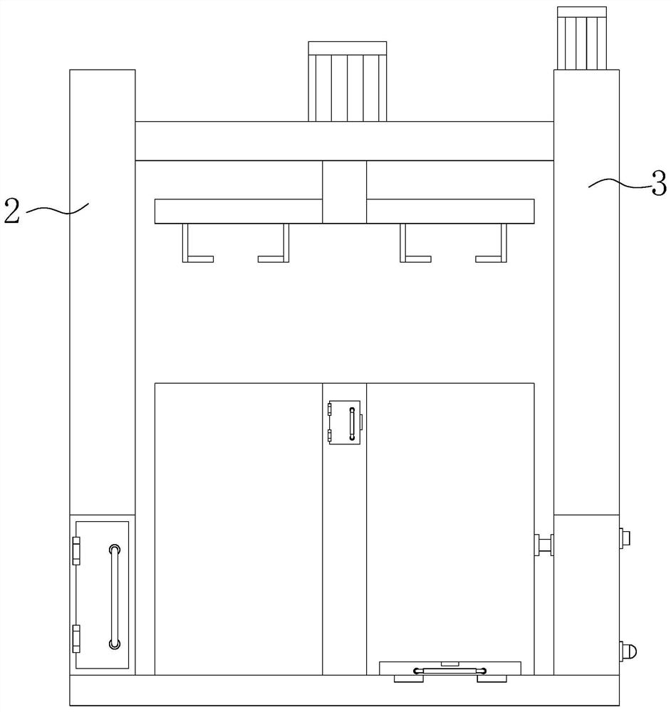
[0029] see Figure 1-8, the present invention provides a technical solution: a heat treatment device for processing conveying machinery parts, including a supporting base plate 1, a first mounting plate 2 and a second mounting plate 3 are arranged on the top of the supporting base plate 1, and a There is a first chute, a sliding bar 38 is fixedly installed in the first chute, and the outer wall of the sliding bar 38 slides and is provided with a first slider 4...


PUM


Abstract

The invention discloses a heat treatment device for conveying machine part machining, and relates to the technical field of conveying machines. The heat treatment device for conveying machine part machining comprises a supporting bottom plate, a first mounting plate and a second mounting plate are arranged at the top of the supporting bottom plate, a first sliding groove is formed in the first mounting plate, and a sliding rod is fixedly mounted in the first sliding groove. According to the heat treatment device for conveying machine part machining, a pipeline can be automatically clamped andfixed, the pipeline does not need to be heated by hand holding, the possibility that a worker is scalded in the operation process is avoided, the labor intensity of the worker is effectively reduced,the safety of the device is enhanced, and the practicability of the device is improved; and the heated pipeline does not need to be directly put into water for cooling manually, the situation that dueto the huge temperature difference, evaporated water mist splashes easily, and consequently workers are scalded is avoided, the labor intensity of the workers is effectively relieved, and the safetyof the device is enhanced.

Description

technical field [0001] The invention relates to the technical field of conveying machinery, in particular to a heat treatment device for processing conveying machinery accessories. Background technique [0002] The full name of conveying machinery is continuous conveying machinery. It is a mechanical device that transports or conveys bulk materials and finished items along a certain line in a continuous, uniform and stable manner. It has low operating costs, fewer braking times, and high efficiency. , easy to control and so on. [0003] The existing processing and heat treatment methods for small parts of conveying machinery are usually manually heated by hand, such as pipes. Manual heating is very dangerous, and it is easy to be scalded if you are not careful, and the efficiency is low, and it is harmful to heated pipes. Put it directly into the water to cool down, the huge difference in temperature is easy to splash the evaporated water mist, and it is also easy to burn t...

Claims


Application Information

Patent Timeline
Patent Type & Authority Applications(China)
IPC IPC(8): C21D1/34C21D9/08B24B55/02B24B41/06B24B5/04
CPCC21D1/34C21D9/085C21D9/0062B24B5/04B24B55/02B24B41/067Y02P10/25
Inventor 吕峰
Owner 泰安市鲁阳金属制品有限公司
Why Eureka
Try Eureka