
Double-rotor linear compressor

A linear compressor and double mover technology, applied in the field of compressors, can solve the problems of difficult elimination and strong penetration, and achieve the effects of easy elimination, small left and right axial vibration, and increased stability

Active Publication Date: 2020-11-10
CHENGDU ELECTRIC MFG CO
View PDF9 Cites 0 Cited by
  • Summary
  • Abstract
  • Description
  • Claims
  • Application Information

AI Technical Summary

Problems solved by technology

[0003] Most of the above-mentioned noises are low-frequency strong vibration noises with strong penetrating power. Even if a muffler is added, it is very difficult to eliminate them.

Method used


Image

  • Double-rotor linear compressor
  • Double-rotor linear compressor
  • Double-rotor linear compressor

Examples


Embodiment Construction

[0027] The present invention will be further described below in conjunction with the accompanying drawings, but the protection scope of the present invention is not limited to the following description.

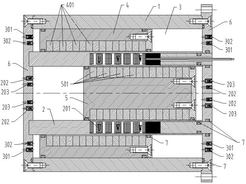
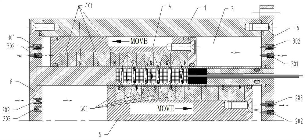
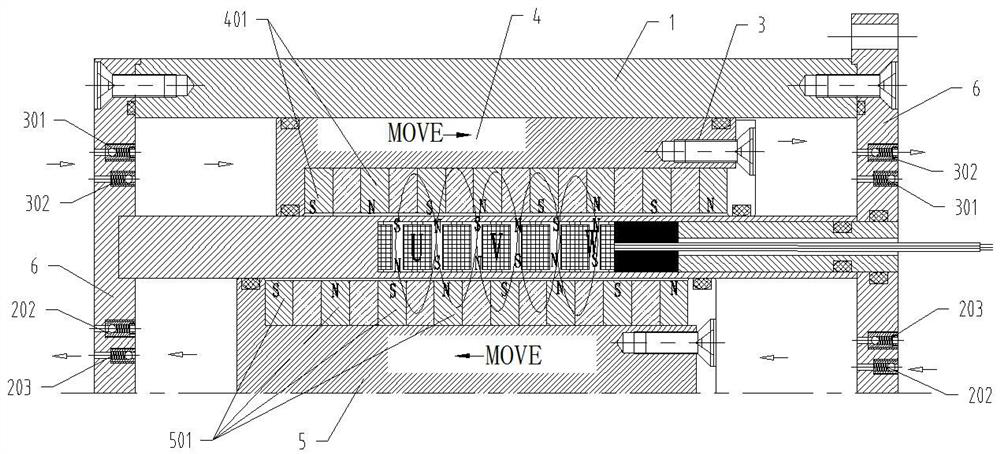
[0028] Such as Figure 1~Figure 4 As shown, a double mover linear compressor includes an outer casing 1, and a cylinder 2 is arranged along the axis inside it, and the two form an annular chamber 3; a piston A4 is arranged in the annular chamber 3, and a cylinder 2 A piston B5 is arranged inside; the left and right ends of the annular chamber 3 and the cylinder 2 are closed by the end cover 6, and the left and right ends of each chamber are provided with corresponding inlet valves and outlet valves. Fluid compression is performed by driving the left and right movements of the piston A4 and the piston B5.

[0029] In this scheme, if figure 1 As shown, a plurality of permanent magnets A401 are arranged at intervals on the piston A4, a plurality of permanent magnets B501 are a...


PUM


Abstract

The invention relates to a double-rotor linear compressor. The double-rotor linear compressor comprises an outer shell body, wherein a cylinder is arranged in the outer shell body along the axis of the outer shell body, and an annular cavity is formed by the outer shell body and the cylinder; a three-phase alternating-current coil winding is arranged on the wall of the cylinder; a piston A is arranged in the annular cavity, and a plurality of permanent magnets A are arranged on the piston A at intervals; a piston B is arranged in the cylinder, and a plurality of permanent magnets are arrangedon the piston B at intervals; the piston A and the piston B carry out left-right action under the electromagnetic action of the three-phase alternating-current coil winding; and one-way air inlet valves A and one-way air outlet valves A are arranged on the left end wall and the right end wall of the cylinder cavity separately, and one-way air inlet valves B and one-way air outlet valves B are arranged on the left end wall and the right end wall of the cylinder separately. The double-rotor linear compressor has the beneficial effects of being low in noise and free from strong vibration noise, facilitating to noise elimination, and being good in cooling effect.

Description

technical field [0001] The invention relates to the technical field of compressors, in particular to a double mover linear compressor. Background technique [0002] Common compressors usually use the impeller to rotate, but the noise is very loud. The blades are arranged at multiple intervals, and the fluid flows in a pulsating state under the action of each blade, which causes the blades to vibrate and emit noise; and the friction between the fluid and the blades, and the fluid and the casing also produces noise; It is shell-shaped, and its inner diameter changes, causing the area where the fluid flows to decrease gradually, which also produces vibration noise; it also includes mechanical noise caused by bearing friction. [0003] Most of the above-mentioned noises are low-frequency strong vibration noises with strong penetrating power. Even if a muffler is added, it is very difficult to eliminate. [0004] For this reason, a double-mover linear compressor is specially de...

Claims


Application Information

Patent Timeline
Patent Type & Authority Applications(China)
IPC IPC(8): F04B35/04F04B27/00F04B39/06F04B39/00F04B39/12H02K16/02
CPCF04B35/04F04B27/005F04B39/06F04B39/0005F04B39/122H02K16/02
Inventor 王立云谢海东石利俊熊雄易双淳刚郭勇
Owner CHENGDU ELECTRIC MFG CO
Learn More