Bearing cage for rolling-element bearing

A technology for bearing cages and rolling elements, applied in rolling contact bearings, rotating bearings, bearings, etc., can solve problems such as inapplicability, increased friction of rolling elements, loss of radial and axial retention of cages, etc., to achieve Low weight, high RPM, easy-to-manufacture effects

Pending Publication Date: 2020-11-10
AB SKF
View PDF0 Cites 0 Cited by
  • Summary
  • Abstract
  • Description
  • Claims
  • Application Information

AI Technical Summary

Problems solved by technology

However, with the bearing cages used hitherto it is possible that at high rotational speeds the retaining elements connecting the two bearing cage halves bend radially outwards so that the cage expands and thus comes into contact with the outer ring , and increase the friction of the rolling elements or cause the rolling elements to seize
Known bearing cages are also not suitable for high loads in radial and axial directions, since both the radial and axial retention of the cage are lost in the event of failure of the retaining elements used

Method used


Image

  • Bearing cage for rolling-element bearing
  • Bearing cage for rolling-element bearing
  • Bearing cage for rolling-element bearing

Examples


Embodiment Construction

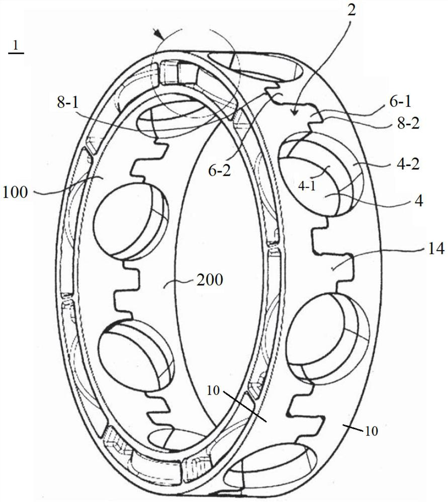
[0071] figure 1 A schematic spatial illustration of a bearing cage 1 for a ball bearing comprising a first bearing cage half 100 and a second bearing cage half 200 is shown. In this case, the bearing cage halves 100 and 200 are designed identically. if possible from figure 1 It is further seen that the bearing cage 1 comprises bridges 2 between which are formed cage pockets 4 in which rolling elements (not shown) can be received. Here, the cage cavity 4 has a circular ring shape; this means that the cage cavity 4 is formed spherically on its radial inside 4-1, while the cage cavity 4 is formed on its radial outside 4-2 as Cylindrical. This annular design enables the rolling elements (i.e. balls) to be well guided on the radially inner side 4-1 and completely enclosed in the cavity 4, while on their radially outer area 4-2 , The rolling elements and the bearing cage 1 have a certain distance, so that the lubricant can penetrate into the gap between the rolling elements and ...


PUM


Abstract

The invention relates to a two-part bearing cage (1) for rolling element bearings, comprising a first cage half (100) and a second cage half (200), preferably of the same construction as the first cage half (100), each comprising an annular base body (10), a projection (6) extending axially therefrom, and a complementarily constructed projection receptacle (8), wherein the projection of one cage half engages in the projection receptacle of the other cage half, the projection forming a bearing cage bridge (2) during engagement in the projection receptacle, the bearing cage bridge forming a bearing cage pocket (4) between them for receiving a rolling element (54) of the rolling element bearing, the protrusions (6) and/or the protrusion receptacles (8) comprise sacrificial material (28) on respective contact surfaces, the sacrificial material being configured to melt under the effect of ultrasonic waves to connect the first cage half to the second cage half.

Description

technical field [0001] The present invention relates to a two-part bearing cage for rolling element bearings according to the preamble of claim 1 . In addition, the present invention relates to an ultrasonic welding device according to technical solution 11. Furthermore, the present invention relates to a bearing cage for a rolling element bearing ( / rolling bearing) according to the preamble of claim 12 . Background technique [0002] For various applications, for example in ball bearings, it is known to use two-part bearing cages consisting of identical bearing cage halves. However, with the bearing cages used hitherto it is possible that at high rotational speeds the retaining elements connecting the two bearing cage halves bend radially outwards so that the cage expands and thus comes into contact with the outer ring , and increase the friction of the rolling elements or cause the rolling elements to get stuck. Known bearing cages are also not suitable for high loads i...

Claims


Application Information

Patent Timeline
Patent Type & Authority Applications(China)
IPC IPC(8): F16C33/38B29C65/08C08L61/16C08L77/06C08K7/06C08K7/14
CPCF16C33/3875B29C65/08C08L61/16C08L77/06F16C2226/38C08K7/06C08K7/14F16C2300/22F16C2208/62F16C2208/36F16C2208/82F16C19/06F16C33/6614F16C33/6651F16C33/4641F16C19/305
Inventor 亚历山大·莫克尼克
Owner AB SKF
Why Eureka
Try Eureka