
Friction clutch for electric drive machine having axis of rotation

A technology of friction clutch and electric drive machine, applied in the direction of friction clutch, mechanical drive clutch, clutch, etc., can solve the problem of limited radial installation space, etc., and achieve the effect of less leftover material share and simple assemblability

Pending Publication Date: 2020-11-10
SCHAEFFLER TECH AG & CO KG
View PDF0 Cites 0 Cited by
  • Summary
  • Abstract
  • Description
  • Claims
  • Application Information

AI Technical Summary

Problems solved by technology

However, there is only a very limited radial installation space here

Method used


Image

  • Friction clutch for electric drive machine having axis of rotation
  • Friction clutch for electric drive machine having axis of rotation
  • Friction clutch for electric drive machine having axis of rotation

Examples


Embodiment Construction

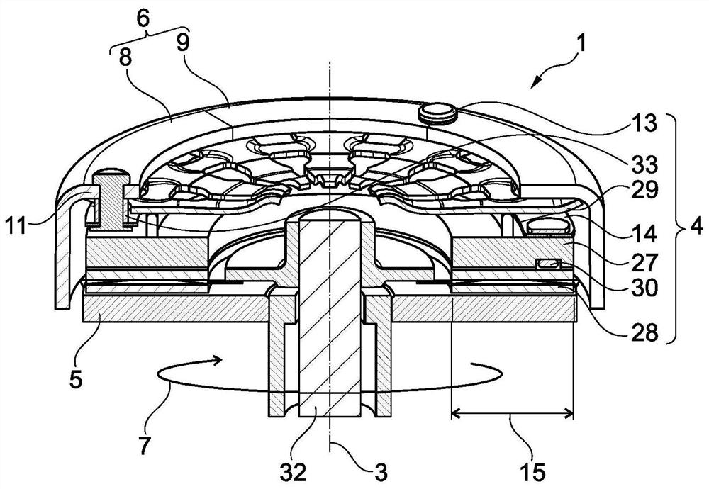
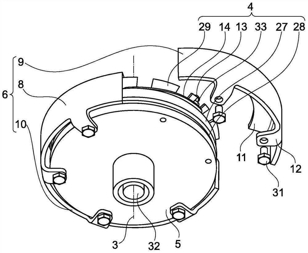
[0048] exist figure 1 The friction clutch 1 is shown in perspective section in the figure 2 Shown in perspective view. The components of the friction clutch 1 are rotatable about a central axis of rotation 3 . As in a conventional friction clutch 1 , when the friction pack 4 is not compressed, the friction disc 28 together with the central shaft, for example the transmission input shaft 32 , can move relative to the clutch cover 6 , the counter plate 5 and the remaining parts of the friction pack 4 . rotate. The friction group 4 here comprises the pressure plate 27 and the friction disk 28 as a friction pair. The friction disk 28 shown here has, in conventional manner, a friction lining on each side and (optionally) a lining spring arrangement in between. For actuation, the friction group 4 (optionally) comprises a lever spring 29, which is supported on the pressure plate 27 (here via the cam ring) and oppositely supported radially as far as possible on the outside at the...


PUM


Abstract

The invention relates to a friction clutch (1) for an electric drive (2) having an axis of rotation (3), comprising at least the following components: a friction pack (4) in a normally open configuration; the counter-pressure plate (5) is used for receiving axial extrusion force; and a clutch cover (6), which is axially fixedly connected to the counter-pressure plate (5) and on which the frictionpack (4) is axially supported, the clutch cover (6) having a plurality of integral sections (8, 9, 10) in the rotational direction (7). The friction clutch (1) is mainly characterized in that each ofthe sections (8, 9, 10) has a first flange (11) on the friction pack side for connecting to the friction pack (4) and a second flange (12) on the counter-pressure plate side for connecting to the counter-pressure plate (5). The friction clutch according to the invention can be easily assembled and disassembled with minimal installation space requirements.

Description

technical field [0001] The invention relates to a friction clutch for an electric drive machine with an axis of rotation, a transmission unit for an electric drive machine with such a friction clutch, an electrified drive for a motor vehicle with such a transmission unit system and a motor vehicle having such an electrified drive system. Background technique [0002] Various embodiments of friction clutches are known from the prior art for detachable torque transmission with adjustable slip. Often the existing installation space is very limited and mountable (dismountable) solutions are sought which can be used in the available installation space. For example, in the case of an electric drive in an electrified or hybrid motor vehicle, the electric drive should not only be connected to the output via a fixed gear stage, but should be able to engage a second gear in order to be able to use the existing engine speed for higher vehicle speeds. A load switching clutch is requi...

Claims


Application Information

Patent Timeline
Patent Type & Authority Applications(China)
IPC IPC(8): F16D13/50F16D13/56F16D13/58F16D13/64F16D13/70F16D13/71
CPCF16D13/50F16D13/56F16D13/58F16D13/64F16D13/648F16D13/70F16D13/71F16D2300/14F16D2300/26F16D13/48F16D13/585
Inventor M·丹霍伊泽
Owner SCHAEFFLER TECH AG & CO KG
Learn More