Clamping stagnation prevention clutch

A clutch and anti-seize technology, applied in clutches, friction clutches, mechanical drive clutches, etc., can solve problems such as stumbling and slow clutch separation, and achieve the effect of eliminating vibrato, avoiding engine braking, and reducing force.

Inactive Publication Date: 2020-11-10
LONCIN MOTOR +1
View PDF6 Cites 1 Cited by
  • Summary
  • Abstract
  • Description
  • Claims
  • Application Information

AI Technical Summary

Problems solved by technology

[0005] In view of this, the present invention provides an anti-seizing clutch, which solves a series of problems caused by the slippage caused by the reserve coefficient and the frustration problem caused by the slow separation of the clutch caused by operations such as downshifting, and at the same time enables the engagement or Fast and smooth separation, no sticking and avoiding ablation, improving the overall performance of the clutch, thereby ensuring vehicle driving safety

Method used


Image

  • Clamping stagnation prevention clutch
  • Clamping stagnation prevention clutch
  • Clamping stagnation prevention clutch

Examples


Embodiment Construction

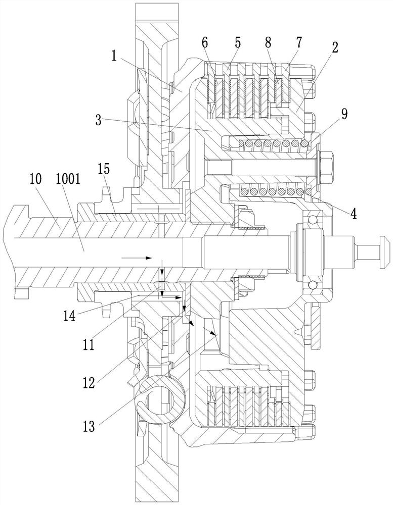
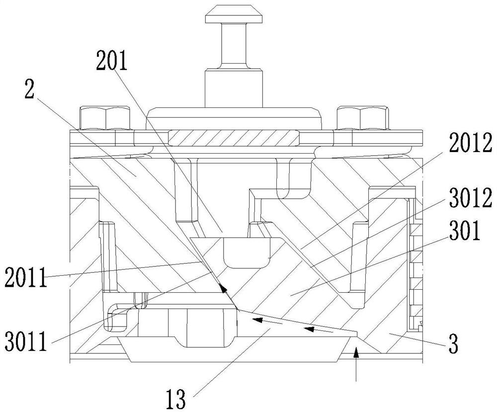
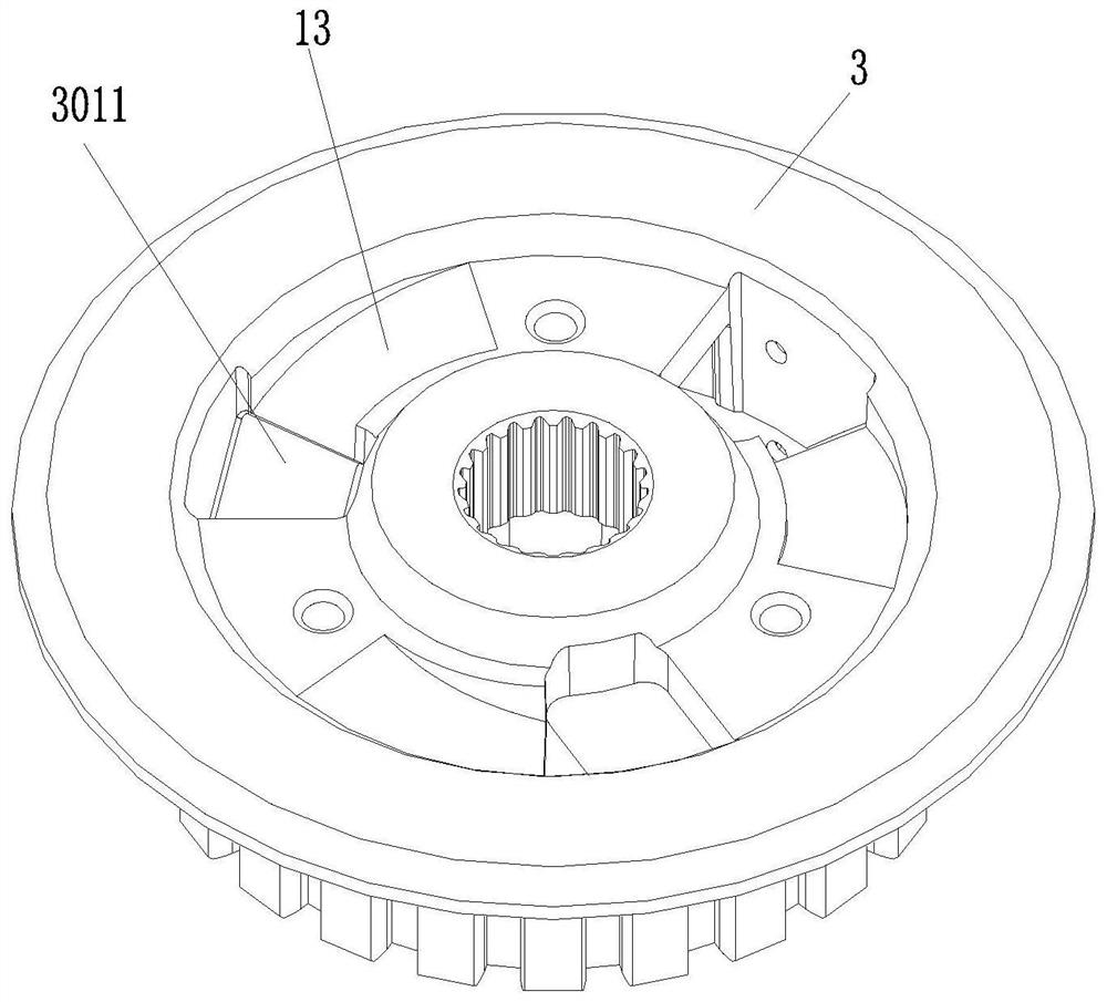
[0036] As shown in the figure, the anti-seize clutch of this embodiment includes a pressure plate 2, a friction plate assembly and a center sleeve 3; including a pressure plate, a friction plate assembly and a center sleeve;

[0037] There is a clearance for relative rotation in the circumferential direction between the pressure plate and the center sleeve, and the engagement between the pressure plate and the center sleeve is formed by an end helical tooth meshing pair;

[0038] The clutch also includes a helical tooth lubricating channel for leading lubricating oil to the helical tooth meshing pair on the end face;

[0039] The structure of the clutch belongs to the prior art, and certainly includes an outer cover 1, a pressure plate 2, a center sleeve 3, a lifting plate 9, a main spring 4, and a friction plate assembly (the active friction plate 5 is arranged on the outer cover 1, and the driven friction plate 6 is arranged on the center sleeve 3 ) and other parts, the pres...


PUM


Abstract

The invention discloses a clamping stagnation prevention clutch. The clutch comprises a pressing plate, a friction plate assembly and a central sleeve. A clearance capable of relatively rotating in the circumferential direction is formed between the pressing plate and the central sleeve, and the pressing plate is meshed with the central sleeve through an end surface helical tooth meshing pair; andthe clutch further comprises a helical tooth lubrication channel for guiding lubricating oil to the end surface helical tooth meshing pair. According to the clutch, the end surface helical tooth meshing pair is arranged between the pressing plate and the central sleeve, the reserve coefficient is increased, a series of problems existing in clutch sliding abrasion are solved, and the problem of pause feeling caused by slow clutch separation due to gear reduction, accelerator retracting and other operations is solved. An original lubricating system of an engine is used for simply improving andarranging an oil channel for lubricating the end surface helical tooth meshing pair, so that the end surface helical tooth meshing pair is fast and smooth in the jointing and separation process of theclutch, clamping stagnation is prevented, ablation is avoided, the overall performance of the clutch is improved, and therefore the driving safety of a vehicle is guaranteed.

Description

technical field [0001] The invention relates to engine parts or accessory parts, in particular to an anti-sticking clutch. Background technique [0002] The clutch is located between the engine and the gearbox. It is a component in the transmission system that is directly connected to the engine. It is a transmission mechanism used to transmit or cut off power between the engine and the gearbox. [0003] In the existing technology center, in order to improve the performance of the clutch itself, increase the reserve coefficient of the clutch and reduce the anti-drag process when downshifting or decelerating; a helical meshing pair is formed between the pressure plate of the clutch and the center sleeve to increase the reserve coefficient And the smooth sliding of the clutch. However, in actual use, the meshing process of the helical gear meshing pair will have a positive axial movement, and jamming will form between the meshing tooth surfaces, resulting in the final strengt...

Claims


Application Information

Patent Timeline
Patent Type & Authority Applications(China)
IPC IPC(8): F16D13/52F16D13/72F16D13/58F02B61/06
CPCF02B61/06F16D13/52F16D13/58F16D13/72
Inventor 凌磊周良兵蒋博文陈艺方聂川
Owner LONCIN MOTOR
Why Eureka
Try Eureka