Supercharge Your Innovation With Domain-Expert AI Agents!

Projection module and electronic device

A diffractive device and sub-reflection technology, applied in optics, instruments, projection devices, etc., can solve problems such as failure to achieve, and achieve the effect of reducing the impact

Inactive Publication Date: 2020-11-10
NANCHANG OUFEI BIOLOGICAL IDENTIFICATION TECH
View PDF0 Cites 0 Cited by
  • Summary
  • Abstract
  • Description
  • Claims
  • Application Information

AI Technical Summary

Problems solved by technology

[0003] In the existing technology, the full screen is the mainstream selling point of current mobile phones, but there is no mobile phone with a real full screen, and the "perforated screen" or "special-shaped screen" is used to increase the screen ratio of the mobile phone.
As the core device of 3D structured light face recognition: infrared speckle projection module, since there is no breakthrough in technology, this projection module has not yet been implemented under the screen

Method used


Image

  • Projection module and electronic device
  • Projection module and electronic device
  • Projection module and electronic device

Examples


Embodiment Construction

[0030] Embodiments of the present invention are described in detail below, and the embodiments described with reference to the drawings are exemplary, and embodiments of the present invention are described in detail below.

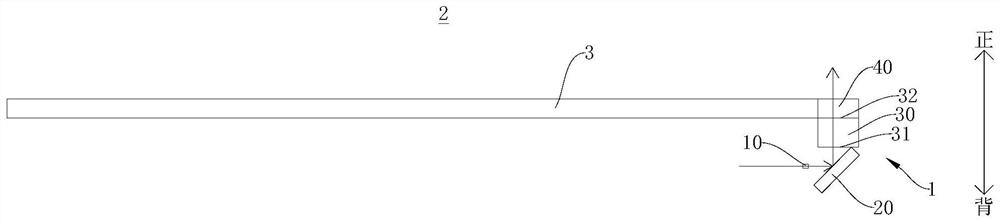
[0031] Refer below Figure 1-Figure 4 The projection module 1 according to the embodiment of the present invention is described. The electronic device 2 includes: a display screen 3 and a projection module 1 , and the projection module 1 is arranged on the back side of the display screen 3 .

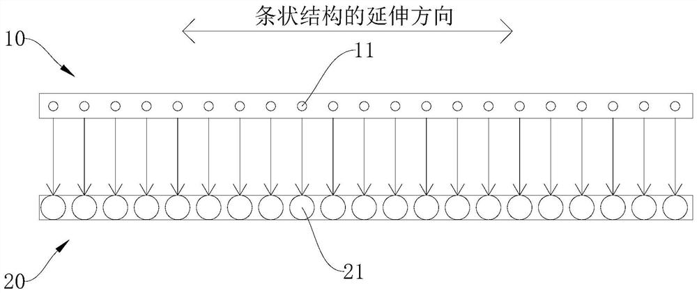
[0032] Such as figure 1 As shown, the projection module 1 according to the embodiment of the present invention includes: a laser emitter 10 , a reflective focusing mirror 20 , a collimating mirror 30 and an optical diffractometer 40 , and the reflective focusing mirror 20 is arranged in the emission path of the laser emitter 10 . The laser emitter 10 emits a beam of light. The reflective focusing mirror 20 is arranged in the emission path of the laser emitter 10 . ...


PUM


Abstract

The invention discloses a projection module. The projection module comprises a laser emitter; a reflection focusing mirror which is arranged in an emission path of the laser emitter; a collimating mirror which is provided with an incident side and an emergent side, wherein the incident side of the collimating mirror corresponds to the emergent direction of the reflection focusing mirror, so the focus of the light reflected by the reflection focusing mirror is formed on the incident side of the collimating mirror; and an optical diffractor which is arranged on the emergent side of the collimating mirror so as to diffract the light collimated by the collimating mirror into a light spot pattern. By arranging the laser emitter, the reflection focusing mirror, the collimating mirror and the optical diffractor, after light is emitted through the reflection focusing mirror, a focus is formed on the incident side of the collimating mirror, at the moment, the emission angle is the smallest; meanwhile, the collimating mirror collimates the light, and finally, the light is diffracted into a light spot pattern through the optical diffractor; when the emission angle is the smallest, the light is the most concentrated; the collimating mirror and the optical diffractor can be narrowest, and the screen-to-body ratio of the projection module to the electronic equipment is reduced to the maximumextent.

Description

technical field [0001] The present invention relates to the technical field of electronic equipment, in particular to a projection module and electronic equipment. Background technique [0002] At present, smart phones are the most popular electronic products. Consumers not only put forward requirements on the functions of mobile phones, but also attach great importance to the appearance of mobile phones. [0003] In the existing technology, the full screen is the mainstream selling point of the current mobile phone, but there is no real full screen mobile phone yet, and the "perforated screen" or "special-shaped screen" is used to increase the screen ratio of the mobile phone. As the core device of 3D structured light face recognition: the infrared speckle projection module, because there is no breakthrough in technology, this projection module has not yet been implemented under the screen. Contents of the invention [0004] The present invention aims to solve at least o...

Claims


Application Information

Patent Timeline
IPC IPC(8): G03B21/20G03B21/14G02B17/02
CPCG02B17/02G03B21/142G03B21/2033
Inventor 王志毛信贤
Owner NANCHANG OUFEI BIOLOGICAL IDENTIFICATION TECH
Features
  • R&D
  • Intellectual Property
  • Life Sciences
  • Materials
  • Tech Scout
  • Unparalleled Data Quality
  • Higher Quality Content
  • 60% Fewer Hallucinations
Learn More