
Control system, tandem controller thereof, multi-frame self-generating switch and control method

A control system and self-generating technology, applied in the direction of electrical components, etc., can solve the problems of inability to control the working state of lamps, flickering, affecting users' use, etc.

Pending Publication Date: 2020-11-10
廖淑辉
View PDF8 Cites 1 Cited by
  • Summary
  • Abstract
  • Description
  • Claims
  • Application Information

AI Technical Summary

Problems solved by technology

However, since the receiving control device is continuously in the signal receiving state, the electrostatic power consumption is relatively large, and a current will be generated in the series loop formed between the receiving control device and the lamp, driving the lamp to generate bright light, As a result, the lamps connected in series with the circuit will produce intermittent flickering when the power is low
For example, if the power of the lamp is 11W, the lamp that is turned off will flicker slightly every 10 seconds in the dark, which not only affects the use of the user, but also shortens the service life of the lamp
In addition, if the power of the lamp is smaller, for example, the power of the lamp is 3W, since the leakage current that the lamp can provide is small, the receiving control device connected in series in the circuit of the lamp may not be able to Start normally, so that the self-generating wireless control switch cannot control the working state of the lamp
[0005] That is to say, although the self-generating wireless control switch with a single live wire has a broad market prospect, the cooperation between the receiving control device of the self-generating wireless control switch and the lamp is still a problem that has not been overcome for a long time.
The reason is that the time for the signal transmitting device of the self-generating wireless control switch to send the control signal is extremely short, usually only a few milliseconds, so in order to avoid missing the control signal, the receiving control device must be kept at The signal receiving state will inevitably lead to an increase in the power consumption of the receiving control device connected in series in the circuit, causing the lamp to be in a dimly lit state or intermittently flickering and cannot be completely turned off
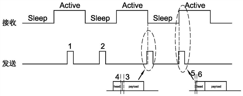
If the receiving control device adopts intermittent dormancy to reduce power consumption, it is easy to miss the opportunity to receive the control signal. After the control signal of the signal transmitting device is transmitted, the receiving control device will Not woken up, causing the fixture in question to not toggle between on and off states properly
In addition, the receiving control device is connected in series in the circuit of the lamp, and the circuit of the lamp provides the electric energy of the receiving control device. If the current required by the receiving control device is slightly larger, for example, the average current reaches AC70uA@220V At this time, the capacitor of the power supply part of the lamp begins to obtain charging current, which may easily cause intermittent flickering of the lamp due to the charging and discharging process of the capacitor

Method used


Image

  • Control system, tandem controller thereof, multi-frame self-generating switch and control method
  • Control system, tandem controller thereof, multi-frame self-generating switch and control method
  • Control system, tandem controller thereof, multi-frame self-generating switch and control method

Examples


Embodiment Construction

[0077] The following description serves to disclose the present invention to enable those skilled in the art to carry out the present invention. The preferred embodiments described below are only examples, and those skilled in the art can devise other obvious variations. The basic principles of the present invention defined in the following description can be applied to other embodiments, variations, improvements, equivalents and other technical solutions without departing from the spirit and scope of the present invention.

[0078] Those skilled in the art should understand that in the disclosure of the present invention, the terms "vertical", "transverse", "upper", "lower", "front", "rear", "left", "right", " The orientation or positional relationship indicated by "vertical", "horizontal", "top", "bottom", "inner", "outer", etc. is based on the orientation or positional relationship shown in the drawings, which are only for the convenience of describing the present invention...


PUM


Abstract

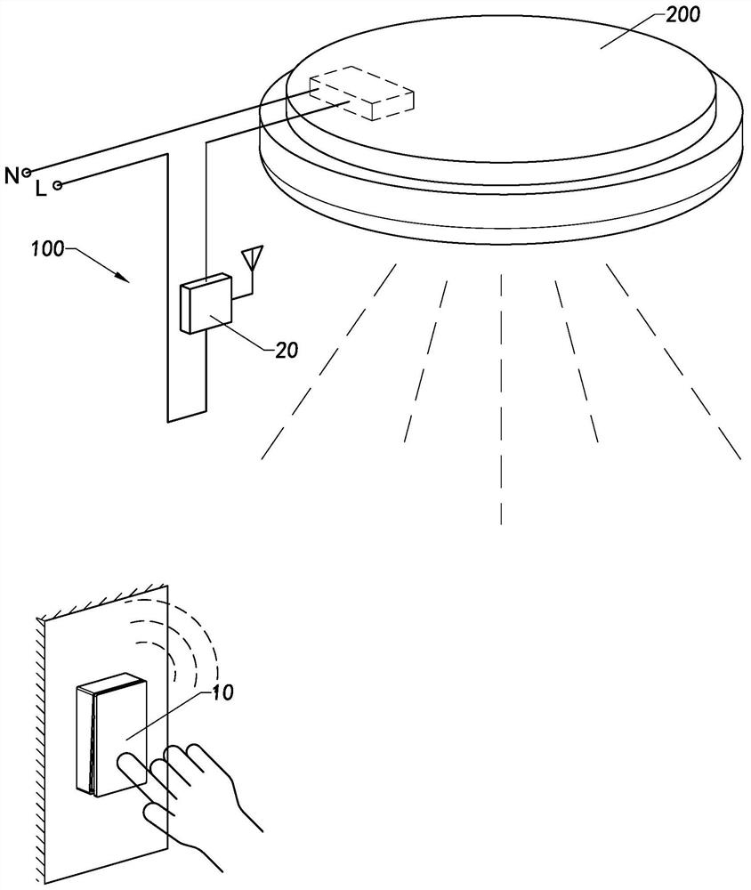
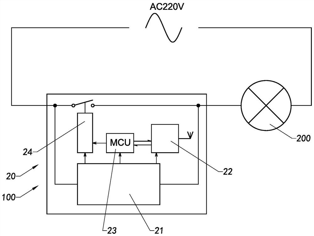
The invention discloses a control system, a tandem controller thereof, a multi-frame self-generating switch and a control method. The control system is suitable for controlling the working state of atleast one electrical device, and the control system comprises the multi-frame self-generating switch and the series controller, wherein the multi-frame self-generating switch comprises a self-generating device and a signal transmitting device, the signal transmitting device is electrically connected to the self-generating device, the signal transmitting device transmits a control signal after obtaining the electric energy supply of the self-generating device, the control signal comprises at least two frames of communication data, and the signal transmitting device transmits the control signalto the self-generating device. The series controller is connected to the electrical equipment in series, the series controller is periodically switched between a dormant state and a receiving state according to a preset rule, and when the series controller is switched to the receiving state, a frame of communication data sent by the self-generating switch is received, and the working state of theelectrical equipment is controlled.

Description

technical field [0001] The invention relates to the field of self-generating wireless switches, in particular to a control system and its serial controller, a multi-frame self-generating switch and a control method. Background technique [0002] The self-generating wireless control switch is widely used in people's daily life and industrial production. It is favored by consumers because it does not need to install batteries, saves money, is environmentally friendly, and is easy to maintain. Specifically, the self-generating wireless control switch includes a signal transmitting device and a receiving control device, wherein the receiving control device is communicably connected to the signal transmitting device, and the receiving control device is connected in parallel in a circuit of a lamp . The signal transmitting device generates a control signal after generating current, and the receiving control device controls the working state of the lamp after receiving the control...

Claims


Application Information

Patent Timeline
Patent Type & Authority Applications(China)
IPC IPC(8): H05B45/30H05B45/50
CPCH05B45/30H05B45/50
Inventor 不公告发明人
Owner 廖淑辉
Learn More