Heat transfer device suitable for space equipment group

An equipment group, heat transfer technology, applied in the direction of modification using liquid cooling, modification through conduction heat transfer, cooling/ventilation/heating modification, etc. Heat dissipation requirements, limited equipment installation surface area, etc., to achieve the effect of solving temperature control problems, high reliability, and suppressing temperature rise

Pending Publication Date: 2020-11-10
SHANGHAI SATELLITE ENG INST
View PDF7 Cites 0 Cited by
  • Summary
  • Abstract
  • Description
  • Claims
  • Application Information

AI Technical Summary

Problems solved by technology

For this method, please refer to the patent ZL201610667666.1 "Integrated Thermal Control Method for Transient Working Standalone with Large Space Heat Consumption". The main disadvantage of this design method is that the area of ​​the equipment installation surface is limited. When the instantaneous heat generation of the equipment is large, Even if the heat dissipation surface is opened on all areas of the equipment installation surface, it cannot meet the heat dissipation requirements of the equipment when it is working.
Another disadvantage of this design method is that it consumes a lot of weight and power resources: the heat pipe network and heat expansion plate take up a lot of weight resources; because the heat dissipation surface is set too large, when the equipment is not working, it is necessary to set up a compensation heater to ensure that the equipment Storage temperature when not in operation, consuming precious power resources

Method used


Image

  • Heat transfer device suitable for space equipment group
  • Heat transfer device suitable for space equipment group
  • Heat transfer device suitable for space equipment group

Examples


Embodiment Construction

[0031] The present invention will be described in detail below in conjunction with specific embodiments. The following examples will help those skilled in the art to further understand the present invention, but do not limit the present invention in any form. It should be noted that those skilled in the art can make several changes and improvements without departing from the concept of the present invention. These all belong to the protection scope of the present invention.

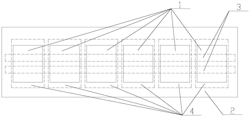
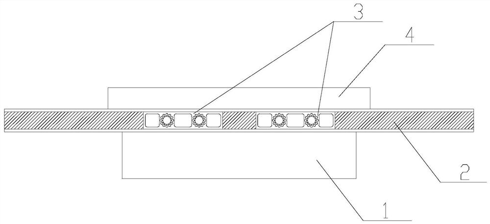
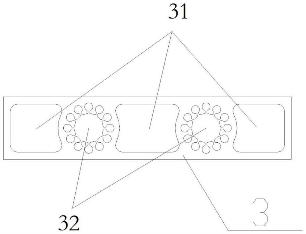
[0032] The invention discloses a heat transfer device suitable for a group of equipment used in space, especially a heat transfer device suitable for a group of short-term high-power devices used in space. The method of combining a phase-change heat pipe with a phase-change energy storage box is effective. It suppresses the temperature rise during the working period of the short-time high-power equipment group, effectively suppresses the temperature rise of the short-time high-power equipment group when ...


PUM


Abstract

The invention provides a heat transmission device suitable for a space equipment group. The heat transmission device comprises the equipment group (1), an aluminum honeycomb plate (2), a phase changeheat pipe (3), and a phase change energy storage box (4). The equipment group (1) is installed on the front face of the aluminum honeycomb plate (2), the phase change heat pipe (3) is pre-buried in aninterlayer of the aluminum honeycomb plate (2), and the phase change energy storage box (4) is installed on the back face of the aluminum honeycomb plate (2). Through the method of combining the phase change heat pipe with the phase change energy storage box, the temperature rise of the short-time high-power equipment group in the working period is effectively inhibited, the startup temperature rise of the short-time high-power equipment group is effectively inhibited, the temperature control problem of the short-time high-power equipment group is solved, and the beneficial effects of high reliability, large phase change material filling amount, good temperature control effect and the like are achieved.

Description

technical field [0001] The invention relates to the field of space vehicle thermal control design, in particular to a heat transfer device suitable for space equipment groups, especially a heat transfer device suitable for space short-term high-power equipment groups. Background technique [0002] Thermal control of short-duration high-power equipment groups used in space is a key issue in the thermal control design of spacecraft. Since the equipment cluster is installed in a small area, it generates a large amount of heat during operation. Without effective thermal control measures, the temperature of the equipment will rise sharply during operation, which will lead to direct failure of the equipment. [0003] The conventional thermal control design method is based on the heat dissipation requirements of the equipment, setting sufficient heat dissipation surfaces in the equipment installation area, and using heat pipe networks and heat expansion plates to evenly heat the he...

Claims


Application Information

Patent Timeline
IPC IPC(8): H05K7/20
CPCH05K7/2029H05K7/2039
Inventor 陈筠力姚正平姜新建郁海勇缪洪康毛云杰郭涛
Owner SHANGHAI SATELLITE ENG INST
Why Eureka
Try Eureka