Tree stump removing device

A tree stump and bolt technology is applied in the field of tree stump removal devices, which can solve the problems of unstable clamping and easy shaking of tree stump removal devices, and achieve the effects of enhancing removal effect, improving stability and saving removal force.

Active Publication Date: 2020-11-13
崔崇岩
View PDF19 Cites 5 Cited by
  • Summary
  • Abstract
  • Description
  • Claims
  • Application Information

AI Technical Summary

Problems solved by technology

[0004] Based on the technical problem that the existing stump removal device is unstable and easy to shake, the present invention proposes a stump removal device

Method used


Image

  • Tree stump removing device
  • Tree stump removing device
  • Tree stump removing device

Examples


Embodiment 1

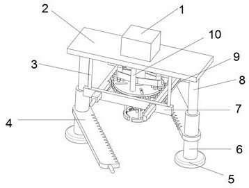
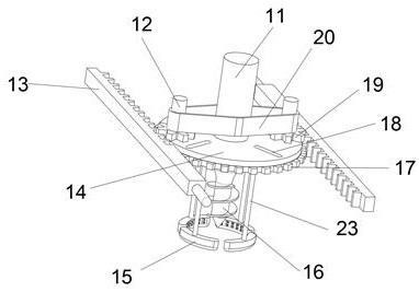
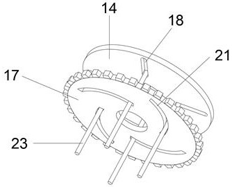
[0025] refer to Figure 1-3 , a tree stump removal device, comprising a support plate 2, a motor 1 is connected to the top outer wall of the support plate 2 by bolts, the motor 1 is fixed with a drilling mechanism, a lifting mechanism is fixed on the bottom outer wall of the support plate 2, and the bottom outer wall of the support plate 2 is connected by bolts There are two pillars 10, the bottom outer wall of the pillar two 10 is connected with a fixed circular plate 14 by bolts, the top of the fixed circular plate 14 is fixed with a linkage mechanism, the bottom outer wall of the fixed circular plate 14 is fixed with a clamping mechanism, and the bottom outer wall of the fixed circular plate 14 is connected by sliding There is a gear plate 17, and the outer wall of the bottom of the support plate 2 is fixed with a transmission mechanism.

[0026] In the present invention, the drilling mechanism includes a rotating shaft 11. The rotating shaft 11 and the output shaft of the ...

Embodiment 2

[0034] refer to Figure 2-4 , a tree stump removal device. Compared with Embodiment 1, the present embodiment includes a clamp ring 15. The clamp ring 15 is connected to the bottom outer wall of the sliding post 23 by bolts. Tooth 22, and the two sides of clamping helical tooth 22 are different with the included angle of clamp ring 15 one side, and the side outer wall that clamps helical tooth 22 and the included angle of one side of clamp ring 15 is connected with cutter tooth 24 by bolt.

[0035] During use, the clamping helical tooth 22 closely fits the tree stump when clamping, and the knife tooth 24 is located on the side with a large angle between the clamping helical tooth 22 and the clamp ring 15, and is opposite to the direction of rotation of the stud 16. When clamping the tree stump, Cutter teeth 24 are embedded in the stump, so that when clamping is more reliable, stud 16 is drilled into the stump to be more stable, which improves the stability of the clamping devi...


PUM


Abstract

The invention discloses a tree stump removing device. Aiming at the problems that the device is unstable to clamp a tree stump and is prone to shaking, the following scheme is provided, the tree stumpremoving device comprises a supporting plate, wherein a motor is connected to the outer wall of the top of the supporting plate through bolts, a drilling mechanism is fixed to the motor, a lifting mechanism is fixed to the outer wall of the bottom of the supporting plate, a second supporting column is connected to the outer wall of the bottom of the supporting plate through bolts, a fixed circular plate is connected to the outer wall of the bottom of the second supporting column through bolts, a linkage mechanism is fixed to the top of the fixed circular plate, and a clamping mechanism is fixed to the outer wall of the bottom of the fixed circular plate. According to the device, the motor drives a rotating shaft to rotate, the transmission belt drives a gear disc to rotate, and sliding grooves and arc grooves move in a staggered mode, so that inner sliding columns move inwards and outwards in the sliding grooves to clamp the tree stump, meanwhile, studs drill into the tree stump to enable the device to be attached to the tree stump more completely, and thus the tree stump is clamped more stably by the device, the situation that the tree stump is failed to be removed and needs to be pulled once more due to that fact that the tree stump is unclamped when being pulled is avoided, and the pulling-out efficiency of the device is improved.

Description

technical field [0001] The invention relates to the technical field of environmental protection, in particular to a stump removal device. Background technique [0002] During the building construction process, some trees or stumps are often encountered, and these trees and stumps need to be cleaned up in the process of leveling the construction site. The traditional cleaning method is to manually dig out trees or stumps, which not only wastes time but also requires a lot of labor costs. Nowadays, various industries are constantly realizing high mechanization. This traditional cleaning method is no longer suitable for current construction needs. [0003] When the existing stump removal device clamps the stump, the device is prone to shaking, which makes the device not stable enough, and when the stump is pulled out, the device is prone to tipping over and even damages the mechanical parts, which is not conducive to the use of the staff. Contents of the invention [0004] B...

Claims


Application Information

Patent Timeline
Patent Type & Authority Applications(China)
IPC IPC(8): A01G23/06
CPCA01G23/065
Inventor 崔崇岩
Owner 崔崇岩
Why Eureka
Try Eureka