
Code scanning detection method for automatic storage code scanning and sorting equipment

A technology of sorting equipment and detection methods, applied in sorting, instruments, induction recording carriers, etc., can solve the problems of inability to store directly, NG products flow out of manufacturers, inconvenient scanning code detection, etc., to shorten the time of loading and reprinting, It is easy to reprint and connect, and the effect of improving detection efficiency

Active Publication Date: 2020-12-29
昆山鸿仕达智能科技股份有限公司
View PDF7 Cites 0 Cited by
  • Summary
  • Abstract
  • Description
  • Claims
  • Application Information

AI Technical Summary

Problems solved by technology

[0005] 1) Since the loading box is a unified standard part and the types of products are diversified, the size of the selected rack will also change accordingly. In this way, when the loading box is taken out of the rack, due to the The standard is uniform. Therefore, when picking and placing racks of different sizes, there will be misalignment or failure to take the disc, which will bring inconvenience to the actual scanning code detection;
[0006] 2) When taking photos and reading codes, it is basically operated on a product-by-product basis, which is not only inefficient, but also easily leads to missed shots or code scans (missed detection) of products, directly causing NG products to flow out of the manufacturer;
[0007] 3) After the racks taken out of the loading box have been tested, they cannot be directly stored in the original loading box. They must be stacked at the detection exit. After all the racks are vacated, the loading box is moved to the inspection At the exit, the retrieving manipulator will store the racks one by one into the loading box. Therefore, in the process of packing after inspection, not only the efficiency of packing is affected, but also the previous packing work must be completed before proceeding. The reclaiming inspection work of the next loading box, which in turn affects the efficiency of inspection

Method used


Image

  • Code scanning detection method for automatic storage code scanning and sorting equipment
  • Code scanning detection method for automatic storage code scanning and sorting equipment
  • Code scanning detection method for automatic storage code scanning and sorting equipment

Examples


Embodiment Construction

[0044] In order to make the above-mentioned purpose, features and advantages of the present application more obvious and understandable, the specific implementation manners of the present application will be described in detail below in conjunction with the accompanying drawings. In the following description, numerous specific details are set forth in order to provide a thorough understanding of the application. However, the present application can be implemented in many other ways different from those described here, and those skilled in the art can make similar improvements without departing from the connotation of the present application, so the present application is not limited by the specific embodiments disclosed below.

[0045] In the description of the present application, it should be understood that the terms "center", "longitudinal", "transverse", "length", "width", "thickness", "upper", "lower", "front", " Back", "Left", "Right", "Vertical", "Horizontal", "Top", "...


PUM


Abstract

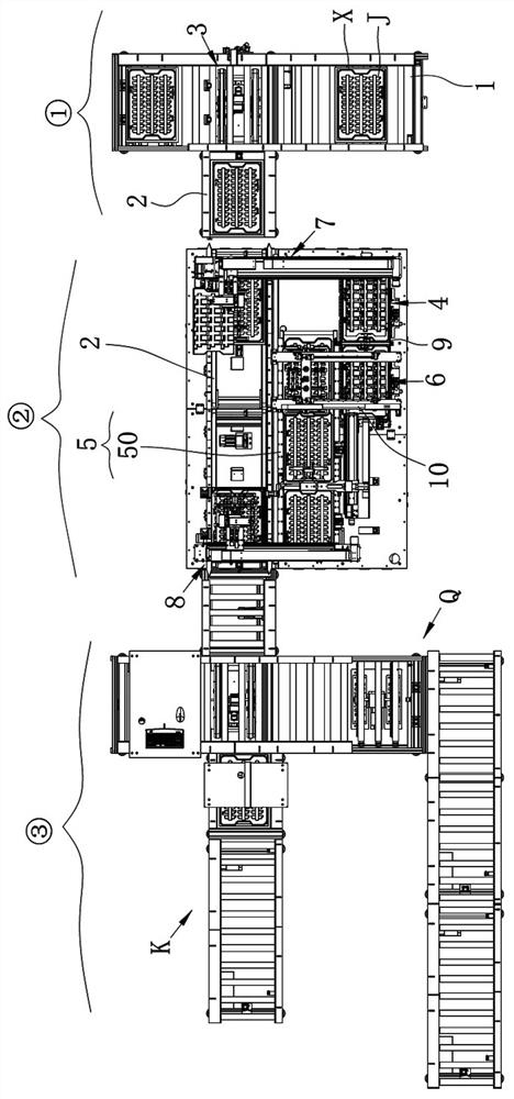
The invention relates to a code scanning detection method of automatic warehousing code scanning classification equipment. The code scanning detection method comprises the following steps that 1) frame trays in a loading box are taken and conveyed to a code scanning feeding station one by one for stacking until the loading box is empty; (2) the stacked frame trays are conveyed forwards in the transverse direction of a transverse moving unit, the stacked frame trays move to the front end of the transverse moving unit, and then a second code scanning and transferring mechanism transversely movesand transfers the frame trays located on the top layer to a code scanning detection station one by one for disc-by-disc code scanning detection; and (3) the frame trays of the corresponding batches can be correspondingly stacked and collected in the original loading box. According to the code scanning detection method, on the premise that it is ensured that each batch of detected products can bestacked and collected to an original loading box, the feeding and transferring time of each batch of frame trays is greatly shortened, meanwhile, the structure of the detection system is simplified and reasonably arranged, the occupied space is small, transferring and joining of the whole batch of frame trays are convenient, and the product detection efficiency is greatly improved. In addition, through a mode of carrying out code scanning detection on each frame tray row by row, it is ensured that missing detection is avoided.

Description

technical field [0001] The invention belongs to the field of code-scanning detection of products, and in particular relates to a code-scanning detection method of automatic storage code-scanning classification equipment. Background technique [0002] At present, for some code-scanning packages that need to be placed on racks, multiple racks are basically stacked in a loading box, and an identification code is formed on the loading box. The specific process is as follows: [0003] Automatic loading, reading the identification code of the loading box (each product corresponds to an identification code) → the system obtains the product type of the whole box → take out a plate from the loading box and take a photo to read the code → check for errors or omissions → After the reading is correct, put them back into the electrostatic box one by one → OK the whole box to flow out, complete the code scanning of each product on the shelf, and then provide a basis for storage. At the sa...

Claims


Application Information

Patent Timeline
Patent Type & Authority Patents(China)
IPC IPC(8): B07C3/00B07C3/02B07C3/10G06K7/10
CPCB07C3/00B07C3/02B07C3/10G06K7/10544
Inventor 胡海东张浩吴玉超
Owner 昆山鸿仕达智能科技股份有限公司
Learn More