Gear chamfering tool assembly and vertical gear chamfering machine

A chamfering machine and chamfering technology, applied in the direction of belt/chain/gear, gear teeth, mechanical equipment, etc., can solve the problems of long switching time, cumbersome tool switching process, etc., to improve processing efficiency, shorten processing auxiliary time, Simple to use effects

Active Publication Date: 2020-11-13
CHONGQING NO 2 MACHINE TOOL WORKS
View PDF19 Cites 2 Cited by
  • Summary
  • Abstract
  • Description
  • Claims
  • Application Information

AI Technical Summary

Problems solved by technology

[0005] The present invention aims to solve the technical problems existing in the prior art. The first purpose of the present invention is to provide a gear chamf

Method used


Image

  • Gear chamfering tool assembly and vertical gear chamfering machine
  • Gear chamfering tool assembly and vertical gear chamfering machine
  • Gear chamfering tool assembly and vertical gear chamfering machine

Examples


Embodiment 1

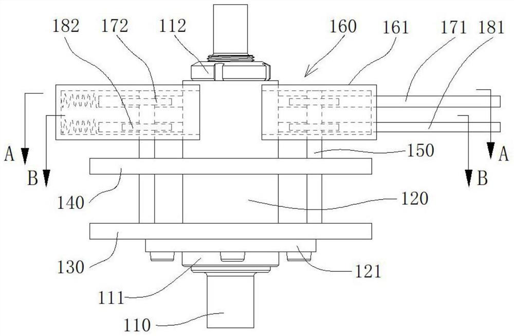
[0041] This embodiment provides a gear chamfering knife assembly, such as figure 1 As shown, in a preferred embodiment, it includes a mandrel 110, the mandrel 110 is sleeved with a knife shaft 120 coaxial with it and axially limited, and the knife shaft 120 is sleeved with a coaxial connection with it The upper cutter head 130 and the lower cutter head 140 are arranged in parallel, and the lower cutter head 140 is located below the upper cutter head 130 . Wherein, the lower cutter head 140 is fixedly connected with the cutter shaft 120. For example, the lower end of the cutter shaft 120 has a flange 121, and the lower cutter head 140 and the flange 121 are fastened and connected by bolts; Fixed and axially movable along the cutter shaft 120 , the gear chamfering cutter assembly also includes a driving mechanism that drives the upper cutter head 130 to move axially on the cutter shaft 120 and has a self-locking function.

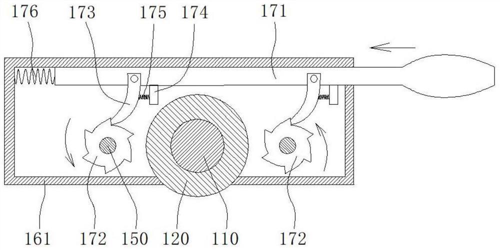
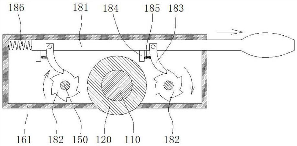
[0042] Wherein, the drive mechanism includes two screw...

Embodiment 2

[0058] This embodiment provides a kind of vertical gear chamfering machine, such as Figure 4As shown, in a preferred embodiment, the vertical gear chamfering machine includes a bed 200, a vertical workpiece spindle 300 installed on the front of the upper end of the bed 200, and a The column 210 , the chamfering module 400 installed on the left front of the column 210 , and the deburring module 500 installed on the right front of the column 210 . The chamfering module 400 includes a chamfering knife assembly 100 and a chamfering knife position adjustment device 410, the chamfering knife assembly 100 is the gear chamfering knife assembly in the first embodiment, the mandrel 110 of the chamfering knife assembly 100 is connected with The workpiece spindles 300 are arranged in parallel, that is, they are all arranged vertically.

[0059] During chamfering, the mandrel 110 is fixed relative to the workpiece spindle 300 , and the cutter shaft 120 is rotatably connected to the mandr...


PUM


Abstract

The invention provides a gear chamfering tool assembly and a vertical gear chamfering machine. The gear chamfering tool assembly comprises a spindle. The spindle is sleeved with a tool shaft coaxial with the spindle and capable of achieving axial limiting. The tool shaft is sleeved with an upper tool disc and a lower tool disc which are coaxially connected with the tool shaft. The lower tool discis fixedly connected with the tool shaft. The upper tool disc is fixed peripherally relative to the tool shaft and can move in the axial direction of the tool shaft. The chamfering tool assembly further comprises a driving mechanism which drives the upper tool disc to move in the axial direction on the tool shaft and has the self-locking function. The driving mechanism drives the upper tool disc to move in the axial direction on the tool shaft so as to adjust the distance between the upper tool disc and the lower tool disc, in order to adapt to the chamfering requirement of gears of differentthicknesses. The gear chamfering tool assembly is easy to operate, the chamfering tool assembly does not need to be disassembled from the gear chamfering machine, the machining auxiliary time is shortened, and the machining efficiency is improved.

Description

technical field [0001] The invention belongs to the technical field of gear processing, and in particular relates to a gear chamfering cutter assembly and a vertical gear chamfering machine. Background technique [0002] The continuous cutterhead full-tooth profile chamfering technology is an efficient and high-quality tooth profile chamfering method, which is widely used in gear chamfering machines. The internal gear tooth profile is continuously extruded, and the metal of the tooth profile is extruded to the end face, and then this part of the metal is cut off from the wheel body with a scraper, so as to realize the chamfering of the gear tooth profile. [0003] For example, CN201310558121.3 discloses a vertical gear chamfering machine, its chamfering knife assembly includes a cutter head, a knife body, a chamfering knife shaft and a sleeve, the knife body is a cylindrical structure, and its outer circumference is provided with a ring The two ends of the web are fixed to ...

Claims


Application Information

Patent Timeline
IPC IPC(8): B23F19/10
CPCB23F19/10
Inventor 张毅刘野黄刚强陈卫
Owner CHONGQING NO 2 MACHINE TOOL WORKS
Why Eureka
Try Eureka