
Male connector U-shaped groove automatic cutting tooling

A technology of automatic cutting and U-shaped grooves, which is applied in the direction of manufacturing tools, metal processing equipment, welding equipment, etc., can solve the problems of inconvenient cutting tooling, increase the labor intensity of users, and reduce the work efficiency of users, etc., to achieve Achieve semi-automatic operation, reasonable tooling structure, and improve efficiency

Pending Publication Date: 2020-11-13
江苏苏建路桥机械有限公司
View PDF0 Cites 0 Cited by
  • Summary
  • Abstract
  • Description
  • Claims
  • Application Information

AI Technical Summary

Problems solved by technology

[0004] The purpose of the present invention is to provide an automatic U-shaped groove cutting tool for male head, so as to solve the problem that the cutting tool proposed in the above background technology is not convenient for loading and unloading of male head, has low efficiency, increases the labor intensity of the user, and reduces the In addition, by adjusting the stack of pads and adjusting the height of the track, the offset between the track, the adjustment pad and the track support channel steel is easy to occur, resulting in the problem of track misalignment

Method used


Image

  • Male connector U-shaped groove automatic cutting tooling
  • Male connector U-shaped groove automatic cutting tooling
  • Male connector U-shaped groove automatic cutting tooling

Examples


Embodiment Construction

[0020] The following will clearly and completely describe the technical solutions in the embodiments of the present invention with reference to the accompanying drawings in the embodiments of the present invention. Obviously, the described embodiments are only some, not all, embodiments of the present invention. Based on the embodiments of the present invention, all other embodiments obtained by persons of ordinary skill in the art without making creative efforts belong to the protection scope of the present invention.

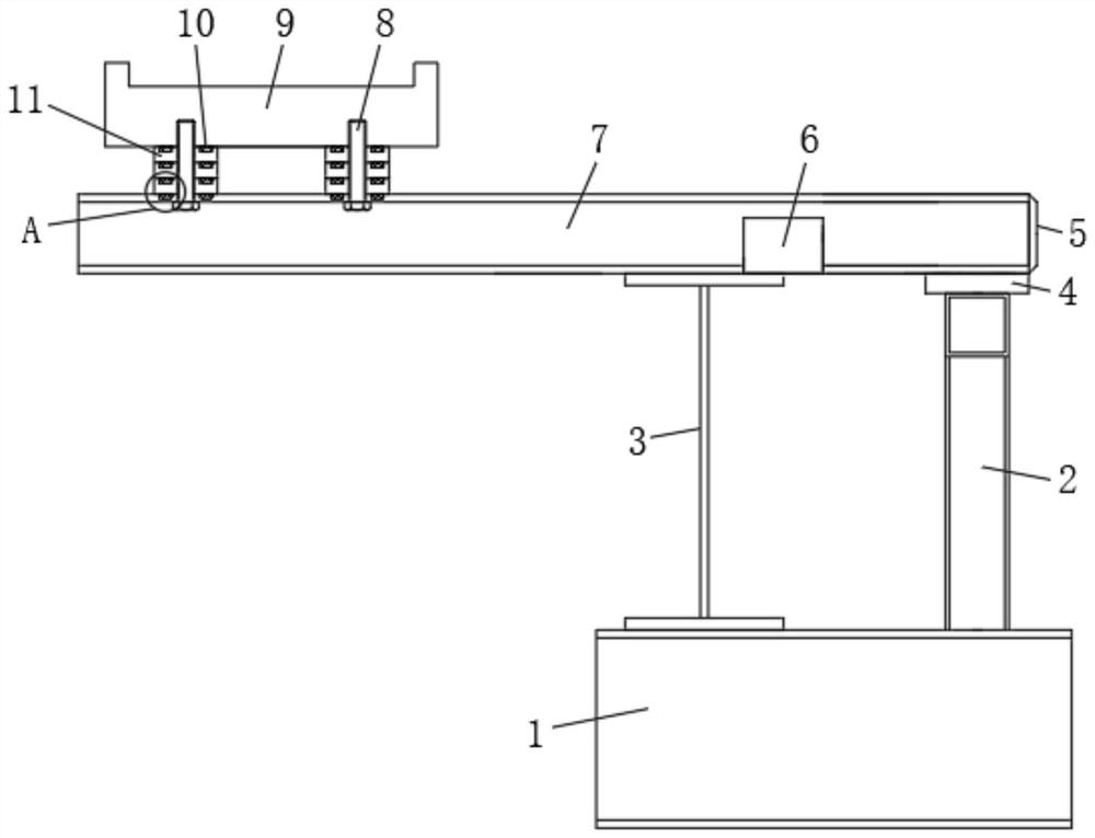
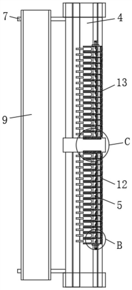
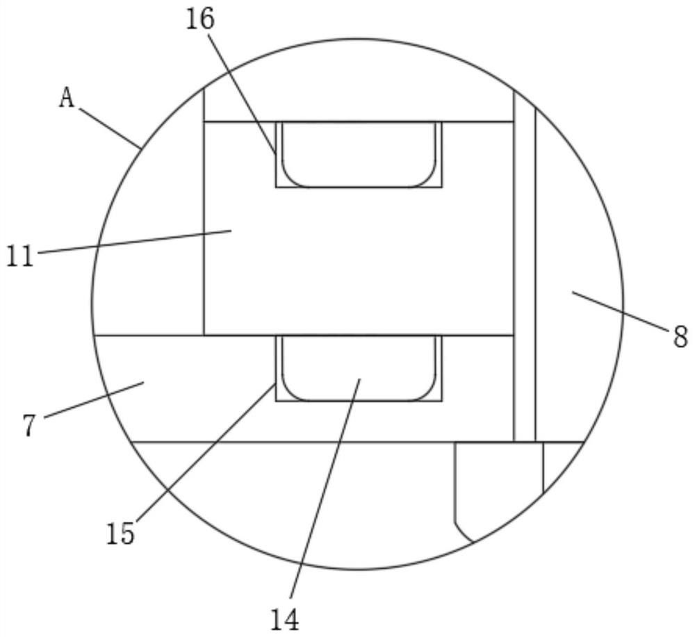
[0021] see Figure 1-Figure 5 As shown, the present invention provides a technical solution: a male head U-shaped groove automatic cutting tool, including a male head placement plane 4, a plane support frame 2 is installed at the bottom of the male head placement plane 4, and the male head placement plane 4 Two rail support channel steels 7 are symmetrically fixed on both sides of the top of the top, and the side of the two track support channel steels 7 close...


PUM


Abstract

The invention discloses a male connector U-shaped groove automatic cutting tooling and relates to the technical field of cutting toolings. The male connector U-shaped groove automatic cutting toolingcomprises a male connector placement plane, wherein a plane supporting frame is mounted at the bottom end of the male connector placement plane; two pieces of rail supporting groove steel are symmetrically fixed on two sides of the top of the male connector placement plane; a workbench main beam is connected with the sides, close to the plane supporting frame, of the two pieces of rail supportinggroove steel; a rail is arranged on the sides, relative to the male connector placement plane, of the tops of the two pieces of rail supporting groove steel; and a workbench column base is mounted atthe bottom ends of both the plane supporting frame and the workbench main beam. The male connector U-shaped groove automatic cutting tooling provided by the invention is reasonable in structure; the rapid cutting of connectors can be achieved; and according to the male connector U-shaped groove automatic cutting tooling, the environmental factors during the manual loading and unloading process aresufficiently considered, so that the working intensity of labors can be effectively reduced, the production efficiency can be greatly improved, and the semi-automatic operation can be achieved.

Description

technical field [0001] The invention belongs to the technical field of cutting tooling, and in particular relates to an automatic cutting tooling for a U-shaped groove of a male head. Background technique [0002] During the automatic cutting process of U-groove of the male head, it is often necessary to clamp it by the cutting tool to facilitate the cutting of the male head. The existing automatic cutting tooling is equipped with portable automatic flame numerical control cutting equipment, and the U-shaped groove of the male head is cut by a special flame to realize the cutting process of the male head. [0003] However, the automatic U-groove cutting tool for male head on the market has defects during use. For example, the cutting tool is not convenient for loading and unloading of the male head, the efficiency is low, and the operation is cumbersome, which increases the labor intensity of the user and reduces the In addition, by adjusting the stack of pads and adjusting...

Claims


Application Information

Patent Timeline
Patent Type & Authority Applications(China)
IPC IPC(8): B23K7/10
CPCB23K7/10
Inventor 李继明
Owner 江苏苏建路桥机械有限公司
Learn More