Transportation device for lithium ion storage battery production

A technology of transportation device and storage battery, which is applied in the direction of transportation and packaging, conveyor objects, loading/unloading, etc., which can solve the problems of increasing manpower consumption and achieve the effect of ensuring work efficiency

Inactive Publication Date: 2020-11-13
湖南三合新能源有限责任公司
8 Cites 6 Cited by

AI-Extracted Technical Summary

Problems solved by technology

[0004] The object of the present invention is to provide a transportation device for lithium-ion storage battery production, to solve the problem that the traditional tra...

Method used

As shown in Figure 1-10, the embodiment provided by the present invention: a kind of transportation device for lithium ion storage battery production, comprises device main body 100, and device main body 100 comprises support column main body 110, and two groups of support column main bodies 110 tops are all A guardrail 120 is fixedly connected, a conveyor belt main body 130 is fixedly connected between the two sets of guardrails 120, a material storage mechanism 200 is arranged on the top of the guardrail 120, and the material storage mechanism 200 includes a material storage tank 210, and the left end of the guardrail 120 is fixedly connected with a The storage tank 210, the storage hopper 220 is fixedly connected to the top of the storage tank 210, the first channel 230 is fixedly connected to the bottom of the storage hopper 220, and the first channel 230 is inserted into the inside of the storage tank 210, the bottom of the first channel 230 The second channel 240 is fixedly connected, and the right end of the material storage tank 210 is fixedly connected with the discharge port 250. Through this mechanism, the operator only needs to regularly replenish the raw materials inside the storage hopper 220, and the device can automatically discharge the material, reducing the To reduce the labor intensity of the operator, a reciprocating mechanism 300 is arranged inside the storage tank 210, and the reciprocating mechanism 300 includes a fixed plate 310, the inner wall of the rear end of the material storage tank 210 is fixedly connected to the fixed plate 310, and the top of the fixed plate 310 is fixedly connected to a motor 320 , and the front end of the motor 320 is fixedly connected with the rotating shaft 330, the front end of the rotating shaft 330 is fixedly connected with the turntable 340, the front end of the turntable 340 is hinged with a hinged rod 350, and the other end of the hinged rod 350 is hinged with a first rack 360, the front end of the storage tank 210 The inner wall bearing is connected with the first rotating rod 370, and the rear end of the first rotating rod 370 is fixedly connected with the first gear 380, and the outer wall of the first gear 380 meshes with the first rack 360. Through this mechanism, the rotation of the motor 320 is used to make the The first gear 380 rotates positively and negatively. The material storage tank 210 is provided with a blanking mechanism 400 inside, and the blanking mechanism 400 includes a second gear 410. The outer wall of the first rotating rod 370 is fixedly connected with the second gear 410, and the second gear The top of 410 is meshed with a second rack 420, the second rack 420 is inserted inside the storage hopper 220, the bottom of the second gear 410 is meshed with a third rack 430, and the third rack 430 is inserted inside the storage hopper 220 , it can be discharged quantitatively, so that the interval between each group of batteries is the same, which ensures the work efficiency. It solves the problem that the current transportation device for lithium-ion battery production is generally used in the assembly of batteries, and prevents the batteries from being connected to the surface of the conveyor belt. Transmission, so that it can be assembled automatically, but the traditional transportation device requires the operator to be on the conveyor belt for a long time to feed, which increases the labor cost of the device, and because the artificial feeding rate is relatively unstable, the overall work efficiency is reduced. Guarantee The working efficiency of the device is improved, the time of the operator is released, and the dependence on artificial feeding is reduced. The operator only needs to put a certain amou...

Abstract

The invention relates to the technical field of transportation devices, in particular to a transportation device for lithium ion storage battery production. The transportation device comprises a device main body, the device main body comprises support column main bodies, protective guards are fixedly connected to the top ends of the two support column main bodies, a conveyor belt main body is fixedly connected between the two protective guards, and a storage mechanism is arranged at the top ends of the protective guards. According to the transportation device, the problems that an existing transportation device for lithium ion storage battery production is generally used for assembling storage batteries, the storage batteries are placed on the surface of a conveyor belt to be transmitted and automatically assembled, and the traditional transportation device needs an operator to be located at the position of the conveyor belt for feeding for a long time, so that the labor cost of the traditional transportation device is increased; and due to the fact that the manual feeding rate is not stable, the overall working efficiency is reduced are solved; the working efficiency of the deviceis guaranteed; the time of an operator is released; the dependence on manual feeding is reduced; and the operator only needs to feed a certain amount of raw material into a storage hopper.

Application Domain

Technology Topic

Image

  • Transportation device for lithium ion storage battery production
  • Transportation device for lithium ion storage battery production
  • Transportation device for lithium ion storage battery production

Examples

  • Experimental program(1)

Example Embodiment

[0029] The following will clearly and completely describe the technical solutions in the embodiments of the present invention with reference to the accompanying drawings in the embodiments of the present invention. Obviously, the described embodiments are only some, not all, embodiments of the present invention. Based on the embodiments of the present invention, all other embodiments obtained by persons of ordinary skill in the art without making creative efforts belong to the protection scope of the present invention.
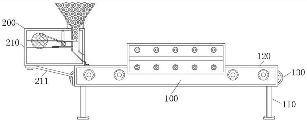
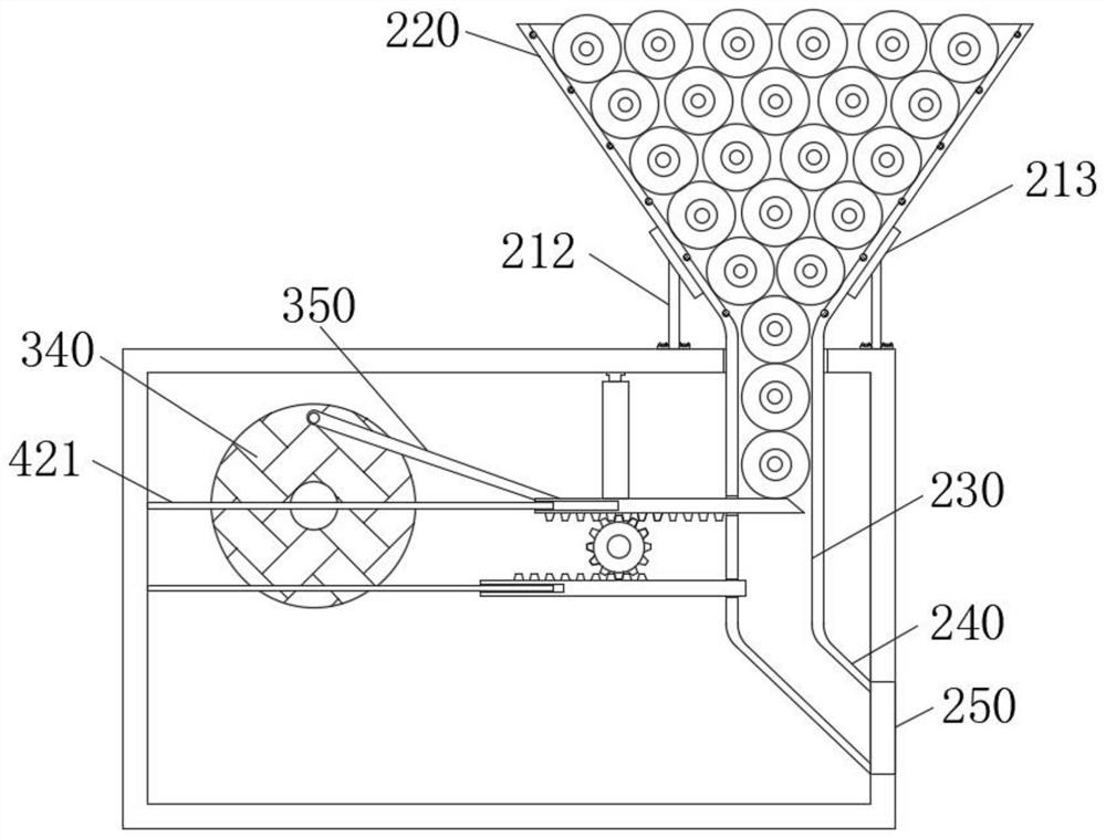
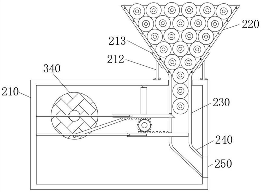
[0030] like Figure 1-10As shown, the embodiment provided by the present invention: a transportation device for lithium-ion storage battery production, including a device main body 100, the device main body 100 includes a support column main body 110, and the tops of two sets of support column main bodies 110 are fixedly connected with guardrails 120. The conveyor belt main body 130 is fixedly connected between the guardrails 120 of the group, and the top of the guardrails 120 is provided with a material storage mechanism 200, and the material storage mechanism 200 includes a material storage tank 210, and the left end of the guardrail 120 is fixedly connected with a material storage tank 210, and the material storage tank The top of 210 is fixedly connected with the storage hopper 220, the bottom of the storage hopper 220 is fixedly connected with the first channel 230, and the first channel 230 is inserted into the interior of the storage tank 210, the bottom of the first channel 230 is fixedly connected with the second channel 240, The right end of the material storage tank 210 is fixedly connected with a discharge port 250. Through this mechanism, the operator only needs to regularly replenish the raw materials inside the storage hopper 220, and the device can automatically discharge the material, which reduces the labor intensity of the operator. A reciprocating mechanism 300 is arranged inside the material tank 210, and the reciprocating mechanism 300 includes a fixed plate 310, the inner wall of the rear end of the material storage tank 210 is fixedly connected with a fixed plate 310, the top of the fixed plate 310 is fixedly connected with a motor 320, and the front end of the motor 320 is fixedly connected with a Rotary shaft 330, the front end of the rotating shaft 330 is fixedly connected with the turntable 340, the front end of the turntable 340 is hinged with a hinged rod 350, and the other end of the hinged rod 350 is hinged with a first rack 360, and the inner wall bearing at the front end of the storage tank 210 is connected with a first rotary rod 370, and the rear end of the first rotating rod 370 is fixedly connected with the first gear 380, the outer wall of the first gear 380 meshes with the first rack 360, through this mechanism, the rotation of the motor 320 is used to make the first gear 380 rotate positively and negatively , the storage tank 210 is provided with a blanking mechanism 400 inside, and the blanking mechanism 400 includes a second gear 410, the outer wall of the first rotating rod 370 is fixedly connected with the second gear 410, and the top of the second gear 410 is meshed with a second rack 420, the second rack 420 is inserted inside the storage hopper 220, the bottom end of the second gear 410 is meshed with a third rack 430, and the third rack 430 is inserted inside the storage hopper 220, and the material can be discharged quantitatively, so that The interval between each group of batteries is the same, which ensures the working efficiency. It solves the problem that the current transportation device for lithium-ion battery production is generally used in the assembly of batteries. However, the traditional transportation device requires the operator to be on the conveyor belt for a long time to feed, which increases the labor cost of the device, and because the artificial feeding rate is relatively unstable, the overall work efficiency is reduced, which ensures the work efficiency of the device and releases The operator's time reduces the dependence on artificial feeding, and the operator only needs to put a certain amount of raw materials into the storage hopper 220 .
[0031] The left end of the guardrail 120 is fixedly connected with a first support rod 211, and the other end of the first support rod 211 is fixedly connected with the bottom end of the storage tank 210. Through this mechanism, through the action of the first support rod 211, the storage tank is further lifted. The stability of 210 after installation ensures the stable discharge of the device.
[0032] Two sets of second support rods 212 are fixedly connected to the top of the storage tank 210, and support plates 213 are fixedly connected to the tops of the second support rods 212, and the ends of the two sets of support plates 213 away from the second support rods 212 are fixedly connected to the storage hopper The outer wall of 220 ensures the stability of the storage hopper 220 through the action of the second support rod 212 and the support plate 213, and prevents the storage hopper 220 from shaking when feeding.
[0033] The top of the storage tank 210 is provided with a first chute 361 , and the inside of the first chute 361 is slidably connected with a first slider 362 , and the end of the first slider 362 away from the first chute 361 is fixedly connected with a first connecting rod 363 , and the bottom end of the first connecting rod 363 is fixedly connected to the first rack 360, through the action of the first sliding block 362 sliding inside the first chute 361, the stability of the first connecting rod 363 when moving is improved, thereby lifting This ensures the stability of the first rack 360 when moving left and right.
[0034] Both the second rack 420 and the third rack 430 are provided with limiting grooves 421 inside, and the limiting rods 422 are inserted inside the limiting grooves 421, and the other ends of the two sets of limiting grooves 421 are fixedly connected to the left end of the storage tank 210 The inner wall, through the action of the limiting groove 421 and the limiting rod 422, limits the movement of the second rack 420 and the third rack 430, ensuring that the second rack 420 and the third rack 430 move left and right. stability.
[0035] The inner sides of the two sets of guardrails 120 are all provided with a limit mechanism 500, and the limit mechanism 500 includes a sleeve 510. The inner walls of the two sets of guardrails 120 are all fixedly connected with the sleeve 510, and the inner walls of the sleeve 510 are fixedly connected with a spring 520, and the spring 520 The other end is fixedly connected with the limiting plate 550, the front end of the limiting plate 550 is fixedly connected with the second connecting rod 540, and the second connecting rod 540 is inserted inside the sleeve 510, the front end of the second connecting rod 540 is fixedly connected with the limiting plate 550, Through this mechanism, it is ensured that the battery can be transported in a directional manner during transportation, avoiding the deviation of the movement track of the battery and causing blockage, and improving the stability of the device during material delivery.
[0036] A second sliding slot 511 is provided inside the sleeve 510, and a second sliding block 512 is slidably connected inside the second sliding slot 511. The end of the second sliding block 512 away from the second sliding slot 511 is fixedly connected to the connecting plate 530. The function of the second sliding block 512 sliding inside the second sliding groove 511 improves the stability of the connecting plate 530 when moving back and forth.
[0037] There is a groove 551 inside the limiting plate 550, and the inner bearing of the groove 551 is connected with a second rotating rod 552, and the outer wall of the second rotating rod 552 is fixedly connected with a ball 553. When the battery contacts the limiting plate 550, the ball 553 is driven and the second rotating rod 552 to reduce the frictional force between the battery and the limiting plate 550 and guide the battery.
[0038] The shape of the right end of the second rack 420 is set to be inclined. When the second rack 420 moves to the right, the battery can be prevented from hindering the second rack 420, and the shape of the second channel 240 is set to be inclined to avoid the battery at the second Blockage occurs inside the second channel 240 .
[0039] Working principle: when discharging is required, start the motor 320, drive the motor 320, the rotating shaft 330 and the turntable 340 to rotate, and through the action of the hinge rod 350, drive the first rack 360 to reciprocate, through the first rack 360 and The meshing effect of the first gear 380 drives the first rotating rod 370 and the first gear 380 to rotate positively and negatively. Through this mechanism, the rotation of the motor 320 is used to make the first gear 380 rotate positively and negatively. Drive the second gear 410 to rotate. When the second gear 410 rotates forward, the second rack 420 moves to the left, the third rack 430 moves to the right, and a set of batteries falls inside the first channel 230 , when the second gear 410 rotates in the opposite direction, the second rack 420 moves to the right, and the third rack 430 moves to the left. At this time, the second rack 420 closes the first channel 230, and the third rack 420 The battery on the surface of the bar 430 falls to the surface of the conveyor belt main body 130 through the outlet 250;
[0040] When the battery shifts when the surface of the main body 130 of the conveyor belt moves, the limit plate 550 is moved towards the guardrail 120 due to the collision, driving the second connecting rod 540 and the connecting plate 530 to move towards the guardrail 120, and the spring 520 is deformed , through the elastic action of the spring 520, the battery can be pushed to reset, and the operation is over.
[0041] It will be apparent to those skilled in the art that the invention is not limited to the details of the above-described exemplary embodiments, but that the invention can be embodied in other specific forms without departing from the spirit or essential characteristics of the invention. Accordingly, the embodiments should be regarded in all points of view as exemplary and not restrictive, the scope of the invention being defined by the appended claims rather than the foregoing description, and it is therefore intended that the scope of the invention be defined by the appended claims rather than by the foregoing description. All changes within the meaning and range of equivalents of the elements are embraced in the present invention. Any reference sign in a claim should not be construed as limiting the claim concerned.

PUM

no PUM

Description & Claims & Application Information

We can also present the details of the Description, Claims and Application information to help users get a comprehensive understanding of the technical details of the patent, such as background art, summary of invention, brief description of drawings, description of embodiments, and other original content. On the other hand, users can also determine the specific scope of protection of the technology through the list of claims; as well as understand the changes in the life cycle of the technology with the presentation of the patent timeline. Login to view more.

Similar technology patents

Classification and recommendation of technical efficacy words

  • Guaranteed work efficiency

Adjustable composite pressure-boosting air intake system

InactiveCN103306805AGuaranteed work efficiencyImproved low-speed torque characteristics and acceleration response characteristicsInternal combustion piston enginesCombustion-air/fuel-air treatmentForced inductionBypass valve
Owner:BEIJING INSTITUTE OF TECHNOLOGYGY

Automatic and efficient gluing device for shoemaking

ActiveCN109123917AThe amount of glue applied is stableGuaranteed work efficiencyShoe gluingPistonEngineering
Owner:泉州卓展商贸有限公司
Why Eureka
Try Eureka