
An environmentally friendly sludge treatment equipment

An environmentally friendly technology for sludge treatment, applied in sludge treatment, water/sludge/sewage treatment, separation methods, etc., can solve sludge difficulties, waste of resources, landfill sludge easily occupies a large area of ​​cultivated land, etc. problems, to achieve the effect of improving practicability and reliability

Active Publication Date: 2021-01-05
海普欧环保集团有限公司
View PDF6 Cites 0 Cited by
  • Summary
  • Abstract
  • Description
  • Claims
  • Application Information

AI Technical Summary

Problems solved by technology

[0002] As we all know, in construction projects, sewage treatment, river improvement and other engineering projects, it is often necessary to clean up the sludge in ponds and other water storage areas, and how to deal with the cleaned up sludge is a relatively difficult problem. The existing sludge treatment method is usually to directly discharge it to low-lying areas and landfill it. However, when this method is adopted, due to the presence of more water and soil components in the sludge, it is easy to cause waste of resources, and at the same time the sludge is landfilled. It is easy to occupy a large area of ​​cultivated land and cause environmental pollution

Method used


Image

  • An environmentally friendly sludge treatment equipment
  • An environmentally friendly sludge treatment equipment
  • An environmentally friendly sludge treatment equipment

Examples


Embodiment Construction

[0020] The specific implementation manners of the present invention will be further described in detail below in conjunction with the accompanying drawings and embodiments. The following examples are used to illustrate the present invention, but are not intended to limit the scope of the present invention.

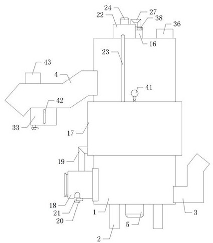
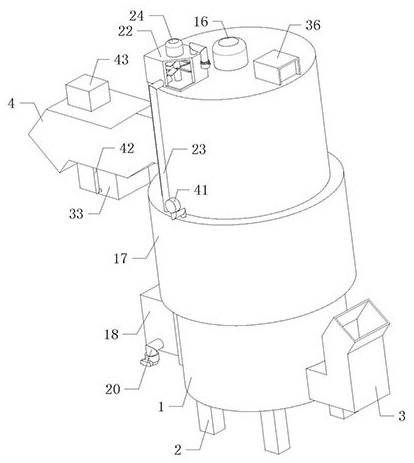
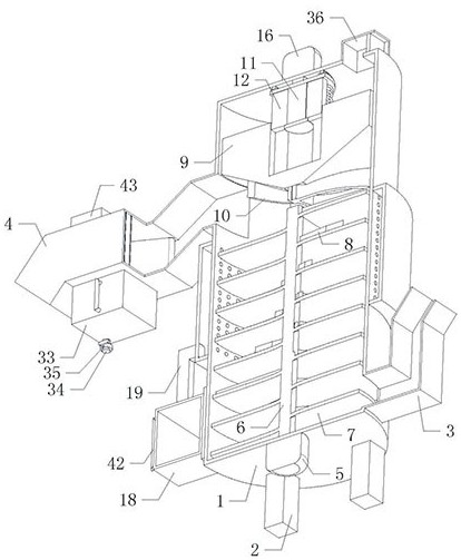
[0021] Such as Figure 1 to Figure 7 As shown, a kind of environment-friendly sludge processing equipment of the present invention, when it is working, open the first motor 5, the first motor 5 drives the pusher shaft 6 to rotate, and the pusher shaft 6 drives the screw pusher piece 7 and multiple groups The baffle plate 8 rotates, the second motor 16 is turned on, and the second motor 16 drives the power plate 14, the sliding shaft 11, two sets of synchronous plates 12 and the limit plate 13 to rotate, and the two sets of synchronous plates 12 drive the pressing material through two sets of synchronous slots The block 9 and the sets of arc-shaped pusher plates 10 on it r...


PUM


Abstract

The present invention relates to the technical field of environmental protection equipment, in particular to an environment-friendly sludge treatment equipment, which can conveniently separate the soil and water in the sludge by dehydrating and drying the sludge, and separate the soil and water conveniently. Recycling, improving resource utilization, saving the cultivated land occupied by landfilling sludge, preventing sludge from damaging the environment, and improving practicability and reliability; including dehydration bins, four sets of legs, feed pipes, outlet The material pipeline, the first motor and the pushing shaft, the four sets of legs are evenly installed on the bottom of the dehydration chamber, the feed pipeline is installed on the lower right side of the dehydration chamber, the discharge pipe is installed on the upper left side of the dehydration chamber, and the first motor is installed at the bottom of the dehydration chamber.

Description

technical field [0001] The invention relates to the technical field of environmental protection equipment, in particular to an environmental protection sludge treatment equipment. Background technique [0002] As we all know, in construction projects, sewage treatment, river improvement and other engineering projects, it is often necessary to clean up the sludge in ponds and other water storage areas, and how to deal with the cleaned up sludge is a relatively difficult problem. The existing sludge treatment method is usually to directly discharge it to low-lying areas and landfill it. However, when this method is adopted, due to the presence of more water and soil components in the sludge, it is easy to cause waste of resources, and at the same time the sludge is landfilled. It is easy to occupy a large area of ​​cultivated land and cause environmental pollution. Contents of the invention [0003] In order to solve the above technical problems, the present invention provi...

Claims


Application Information

Patent Timeline
Patent Type & Authority Patents(China)
IPC IPC(8): C02F11/123B01D46/10B01D46/02B01D46/00
CPCC02F11/123B01D46/10B01D46/02B01D46/62
Inventor 颜炳林
Owner 海普欧环保集团有限公司
Learn More