Sub-nozzle for air jet loom

A technology of air injection and auxiliary nozzles, which is applied in looms, textiles, textiles and papermaking, etc., can solve the problems of small weft yarn conveying force, reduced directivity, and high degree of air flow diffusion, so as to improve conveying force, reduce manufacturing costs, The effect of reducing air consumption

Active Publication Date: 2020-11-13
TSUDAKOMA KOGYO KK
View PDF9 Cites 0 Cited by
  • Summary
  • Abstract
  • Description
  • Claims
  • Application Information

AI Technical Summary

Problems solved by technology

Therefore, in such a sub-nozzle, there is a problem that since the air flow jetted from the injection holes is highly diffused, the directivity of the air flow toward the weft insertion groove decreases accordingly, so the directionality of the air flow relative to the supplied compressed air is reduced. pressure (hereinafter referred to as "supply pressure"
) conveying force of the weft yarn is small

Method used


Image

  • Sub-nozzle for air jet loom
  • Sub-nozzle for air jet loom
  • Sub-nozzle for air jet loom

Examples


Embodiment Construction

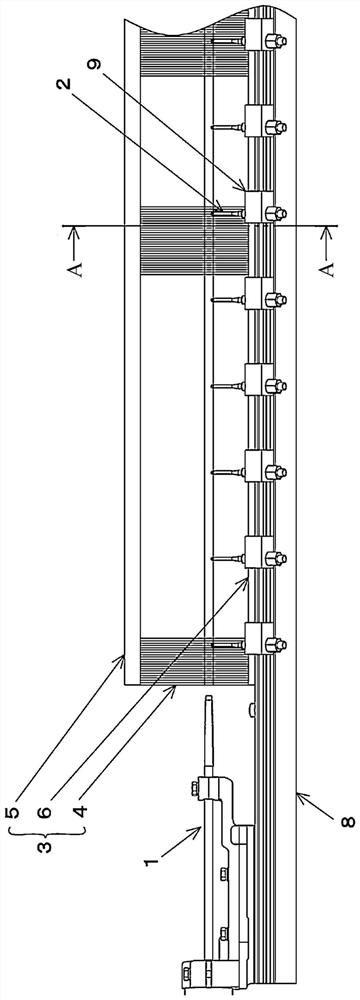
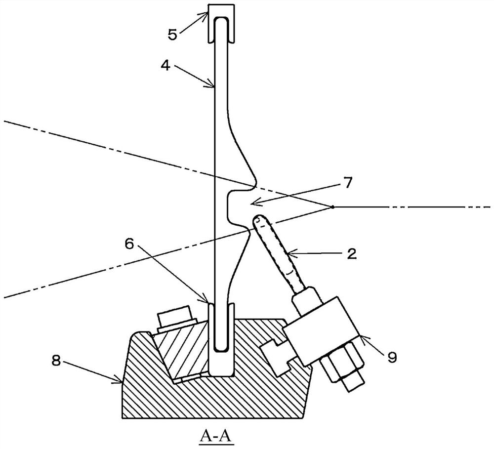
[0040] Such as figure 1 and figure 2 As shown, the air-jet loom to which the sub-nozzle of the present invention is applied includes a main nozzle 1 and a sub-nozzle 2, the main nozzle 1 is used for weft insertion, and a plurality of sub-nozzles 2 are arranged along the shuttle path of the weft yarn. It is used to assist the shuttling of the weft yarn ejected from the main nozzle 1. In addition, this air jet loom includes a reed 3 that beats up the weft yarn that has been picked to a fell of the fabric.

[0041] This reed 3 is a so-called deformed reed, and is configured by providing a plurality of rows of deformed reed teeth 4 having recesses. The deformed reed 3 itself is a well-known structure, so detailed description thereof will be omitted, but each reed tooth 4 has a concave portion formed approximately at the center in the longitudinal direction. Furthermore, each reed tooth 4 is provided in a plurality of rows, and the deformed reed 3 is constituted by being integr...


PUM


Abstract

A sub-nozzle for an air jet loom is provided, the sub-nozzle having a hollow tubular shape having a closed distal end, the sub-nozzle having a distal end portion having an ejection hole (10). In a view in a direction of a center line of the ejection hole, when X is determined as a position that is a position on an outer peripheral edge of the sub-nozzle and that is at a closest distance from a center of the ejection hole, and Y is determined as a position at which a line connecting the center of the ejection hole and the position X intersects with a peripheral edge of the ejection hole, the ejection hole is formed such that a distance between the position X and the position Y is 0.75 mm or less in the view in the direction of the center line. According to the sub-nozzle, a turbulence occurs in a flow of the compressed air in the sub-nozzle, which may adversely affect jetting of the compressed air from the sub-nozzle and lead to a decrease in the conveying force.

Description

technical field [0001] The present invention relates to a sub-nozzle for an air-jet loom. The sub-nozzle is a hollow tubular sub-nozzle with a jet hole formed at the front end and the front end is closed. Background technique [0002] Generally, as described above, the sub-nozzle for an air-jet loom is formed in the shape of a hollow tube with its front end closed, and has an injection hole at the front end. In addition, a plurality of sub-nozzles are arranged along the weft insertion direction on the reed clamp supporting the reed, and enter into the warp yarn opening in the manner of pulling the warp yarn apart as the reed swings during the weaving process. Therefore, the sub-nozzle is formed as a small-diameter nozzle in order to improve the handling of the warp yarn when it enters the warp yarn opening in this way. In addition, accordingly, the wall thickness of the sub-nozzle is very thin, generally 0.5 mm or less. [0003] In addition, in such a sub-nozzle, since the...

Claims


Application Information

Patent Timeline
Patent Type & Authority Applications(China)
IPC IPC(8): D03D47/30
CPCD03D47/302
Inventor 米岛芳之小堀裕一朗
Owner TSUDAKOMA KOGYO KK
Why Eureka
Try Eureka