Thread trimming and presser foot lifting mechanism of sewing machine and sewing machine

A thread-cutting mechanism and presser-lifting technology are applied to thread-cutting mechanism, cloth pressing mechanism, sewing machine components and other directions in sewing machines, which can solve problems such as reducing competitiveness, increasing product production costs, affecting the service life of components, etc. Simple operation, simple post-modification, good heat dissipation protection effect

Pending Publication Date: 2020-11-13
台州市速普机电有限公司
View PDF0 Cites 2 Cited by
  • Summary
  • Abstract
  • Description
  • Claims
  • Application Information

AI Technical Summary

Problems solved by technology

However, in actual work, an oil pan is installed in the chassis, so after the oil pan is removed, the above patented technology can only work in a state of slight oil, which will affect the service life of the components and increase the production cost of the product and reduce the competitiveness

Method used


Image

  • Thread trimming and presser foot lifting mechanism of sewing machine and sewing machine
  • Thread trimming and presser foot lifting mechanism of sewing machine and sewing machine
  • Thread trimming and presser foot lifting mechanism of sewing machine and sewing machine

Examples


Embodiment 1

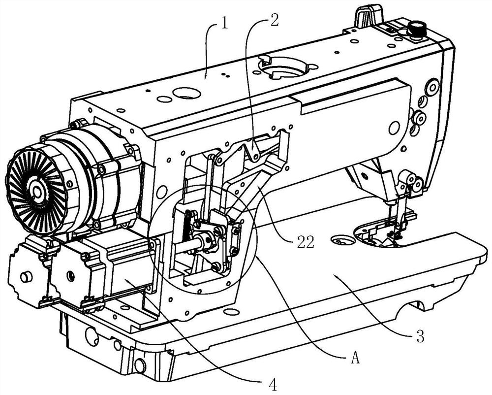
[0036] Embodiment one: if Figure 1-5 As shown, a thread trimming and presser foot lifting mechanism of a sewing machine is provided with a presser foot lifting mechanism 2 at the top of the frame 1, a thread trimming mechanism 32 is provided at the bottom of the frame 1, and a thread trimmer 32 is provided at the middle of the side of the frame The drive motor 4, the motor shaft 5 of the drive motor stretches into the frame 1 and drives the thread trimming mechanism 32 and the presser foot lifting mechanism 2 respectively;

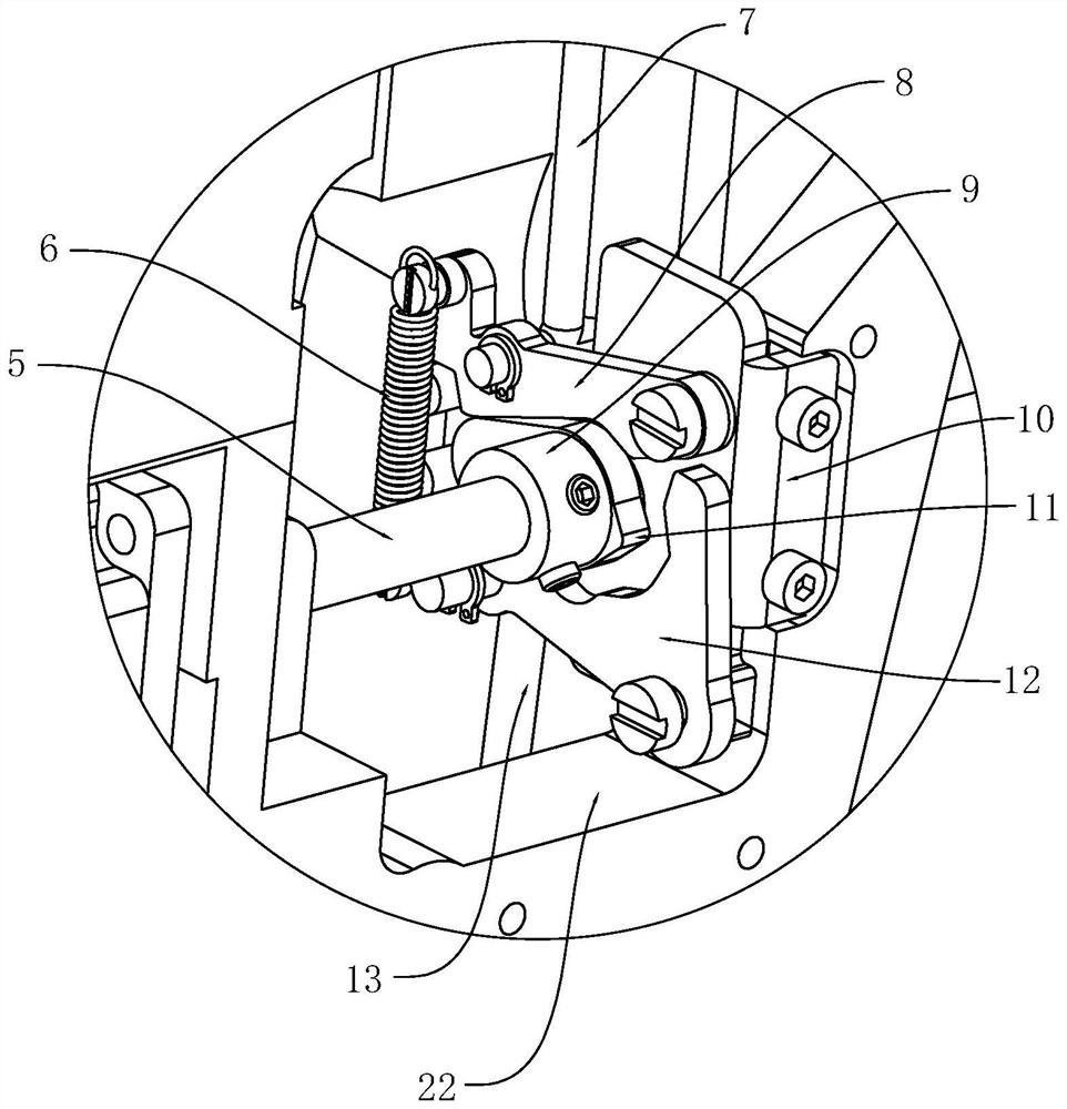
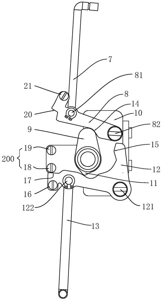
[0037] The motor shaft 5 is provided with a cam 9, the upper side of the cam 9 is provided with a presser foot lifting swing bar 8, and the lower side of the cam 9 is provided with a thread trimmer swing bar 12; Foot fork 8 or thread trimming fork 12, and then respectively drive presser foot lifting mechanism 2 to realize lifting presser foot, or, and then drive thread trimming mechanism 32 to realize automatic thread trimming;

[0038] One end of the pr...

Embodiment 2

[0064] Embodiment 2: This embodiment is basically the same as Embodiment 1, the difference is that: the inner wall of the installation window described in this embodiment refers to figure 2 outside the position of the installation window shown; of course, it can also be installed on the wall of the inner cavity of the rack 1 by changing the shape of the bracket, so that the entire structure can be located inside the installation window, thereby further reducing the impact on the current situation. Due to structural impacts, the existing rear window cover can completely cover the installation window 22 .


PUM


Abstract

The invention discloses a thread trimming and presser foot lifting mechanism of a sewing machine and the sewing machine comprising the thread trimming and presser foot lifting mechanism, and belongs to the technical field of sewing machines. The purpose of the mechanism is achieved by that a frame is provided with a presser foot lifting mechanism and a thread cutting mechanism, a driving motor isarranged in the middle of the side surface of the frame, a motor shaft extends into the frame and drives the thread cutting mechanism and the presser foot lifting mechanism respectively, the upper side of a cam is provided with a presser foot lifting swing rod, and the lower side of the cam is provided with a thread cutting swing rod; the fixed end of the presser foot lifting swing rod is hinged to a bracket, the movable end of the presser foot lifting swing rod is hinged to the end of an upper push rod, the other end of the presser foot lifting swing rod drives the presser foot lifting mechanism, the fixed end of the thread cutting swing rod is hinged to the bracket, the movable end of the thread cutting swing rod is hinged to the top of a lower top bar, the movable end of the presser foot lifting swing rod and the movable end of the thread cutting swing rod are both located on the same side of the frame, one end of a reset spring hooks the movable end of the presser foot lifting swing rod, and the other end of the reset spring hooks the movable end of the thread cutting swing rod.

Description

technical field [0001] The invention belongs to the technical field of sewing machines, in particular to a thread trimming and presser foot lifting mechanism of a sewing machine and a sewing machine including the thread cutting and presser foot lifting mechanism. Background technique [0002] At present, the sewing machine is a tool for combining pieces into garments, which is the core product of the garment manufacturing industry. Therefore, in order to increase sewing efficiency, functions such as automatic thread trimming and automatic presser foot lifting are designed. Later, in order to further reduce the difficulty of operation, a technical solution was designed to achieve linkage between automatic thread trimmer and automatic presser foot lifter. [0003] Such as Chinese patent, patent number: 2016106141869, patent name: a driving device for automatic thread trimmer and automatic presser foot lifter. The above-mentioned patent specifically discloses a driving device...

Claims


Application Information

Patent Timeline
Patent Type & Authority Applications(China)
IPC IPC(8): D05B65/00D05B29/02D05B69/10D05B69/02
CPCD05B29/02D05B65/00D05B69/02D05B69/10
Inventor 蒋达淼任恩林周善足
Owner 台州市速普机电有限公司
Why Eureka
Try Eureka