Channel steel box girder composite girder bridge structure with built-in pipelines and construction method thereof

A technology of steel box girder and pipeline trough, applied in bridges, bridge materials, bridge construction, etc., can solve the problems of affecting the appearance of bridges, long construction period, heavy bridges, etc., and achieve convenient construction, shorten construction period, and beautiful lines. Effect

Pending Publication Date: 2020-11-13
SHENZHEN MUNICIPAL DESIGN & RES INST
View PDF9 Cites 0 Cited by
  • Summary
  • Abstract
  • Description
  • Claims
  • Application Information

AI Technical Summary

Problems solved by technology

The whole bridge looks thick and heavy, which affects the beauty of the bridge; the construction period is long

Method used


Image

  • Channel steel box girder composite girder bridge structure with built-in pipelines and construction method thereof
  • Channel steel box girder composite girder bridge structure with built-in pipelines and construction method thereof
  • Channel steel box girder composite girder bridge structure with built-in pipelines and construction method thereof

Examples


Embodiment 1

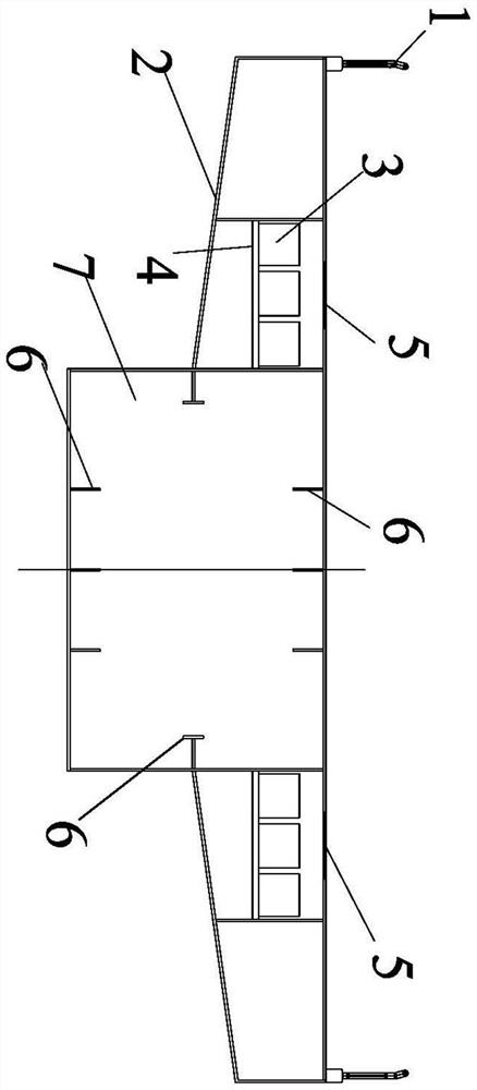
[0032] Such as Figure 1-2 As shown, when the steel box girder composite girder bridge structure is a pedestrian bridge, the flange parts 2 on both sides of the steel box girder 7 are divided into two regions, and the two regions are flanges divided in turn along the outward extension direction of the flange part 2 In order to ensure the torsional rigidity of the bridge, a diaphragm 8 is set at an interval of about 2m, and the diaphragm 8 is usually along the cross section of the bridge. Full cross-section layout, in the present invention, in order to leave space for the pipeline layout, the transverse partition 8 is arranged in the area other than the first flange area, and the horizontal and transverse cross braces 4 are installed in the first flange area, and the pipeline groove 3 is fixed on the horizontal Support 4 on.

[0033] In this embodiment, the cross brace 4 is made of I-shaped steel or channel steel, and the I-shaped steel or channel steel is provided with a slot...

Embodiment 2

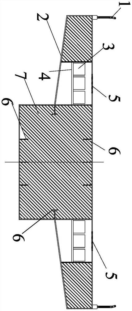
[0035] Such as Figure 3-4 As shown, when the steel box girder composite girder bridge structure is a pedestrian bridge, the flange parts 2 on both sides of the steel box girder 7 are divided into two regions, and the two regions are flanges divided in turn along the outward extension direction of the flange part 2 In order to ensure the torsional rigidity of the bridge, a diaphragm 8 is set at an interval of about 2m, and the diaphragm 8 is usually along the cross section of the bridge. Full cross-section arrangement, in the present invention, in order to leave space for the pipeline layout, the diaphragm 8 is arranged in the area other than the second area of ​​the flange, the second area of ​​the flange is installed with a horizontal and transverse cross brace 4, and the pipeline channel 3 is fixed on the horizontal Support 4 on.

[0036] In this embodiment, the cross brace 4 is made of I-shaped steel or channel steel, and the I-shaped steel or channel steel is provided wi...

Embodiment 3

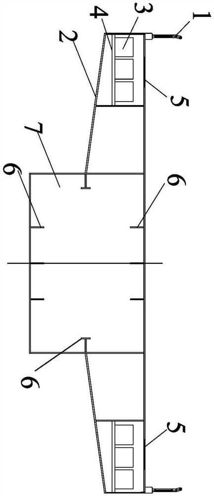
[0038] Such as Figure 5 As shown, when the steel box girder composite girder bridge structure is an urban steel bridge, the flange parts 2 on both sides of the steel box girder 7 are divided into two regions, and the two regions are the wings divided sequentially along the outward extension direction of the flange part 2. Between the first flange area and the second flange area, there is a partition between the first flange area and the second flange area; in order to ensure the torsional rigidity of the bridge, a transverse partition 8 is set at an interval of about 2m, and the transverse partition 8 is usually along the transverse direction of the bridge. The cross-section is arranged in full section. In the present invention, in order to leave space for the pipeline layout, the diaphragm 8 is arranged in the area other than the flange area. According to the maintenance and maintenance requirements, it is considered whether to set up a maintenance channel in the steel box. ...


PUM


Abstract

The invention discloses a steel channel box girder composite girder bridge structure with built-in pipelines and a construction method thereof. The composite girder bridge structure comprises a steelbox girder, a combined bridge deck slab, pipeline grooves, cross braces, access holes and sidewalk guardrails. The horizontally-arranged combined bridge deck slab is installed at the top of the steelbox girder, the cross braces are arranged in the flange parts on the two sides of the steel box girder, the pipeline grooves are fixed to the cross braces, the access holes are formed in the positions, corresponding to the pipeline grooves, of the combined bridge deck slab, and the sidewalk guardrails are fixed to the two sides of the bridge structure. The steel channel box girder composite girderbridge structure with the built-in pipelines is suitable for factory-like prefabrication construction to reduce wind load and bridge section height; the structure has the characteristic of attractiveline type to reduce the weight of an upper sidewalk; and the structure is convenient to construct to shorten the construction period and has good economic benefits.

Description

technical field [0001] The invention relates to the technical field of bridge design and construction, in particular to a built-in pipeline channel steel box girder composite girder bridge structure and a construction method thereof. Background technique [0002] Urban bridges have requirements such as lighting and drainage, and corresponding pipelines need to be laid. In order to lay pipelines, the sidewalk is usually raised, and the pipeline trough is laid under the sidewalk slab. This method of pipeline layout increases the overall vertical height of the bridge, increases the area of ​​the windward side of the bridge, and increases the wind load; since the pipeline layout space is assembled by concrete components, the vertical load on the flange part of the steel box girder is increased . The whole bridge looks thick and heavy, which affects the beauty of the bridge; the construction period is long. Contents of the invention [0003] The purpose of the present inventi...

Claims


Application Information

Patent Timeline
Patent Type & Authority Applications(China)
IPC IPC(8): E01D2/04E01D101/30
CPCE01D2/04E01D2101/30
Inventor 杨曦吴岐贤罗宇孙志国于芳齐花炳林庆辉詹振宇王野伍福兴
Owner SHENZHEN MUNICIPAL DESIGN & RES INST
Why Eureka
Try Eureka