
A concrete railing column at the end of a bridge road with cast-in-place construction

A technology in concrete and concrete, applied in the direction of bridges, bridge parts, bridge construction, etc., can solve the problems of inconvenient construction and installation on site, inconvenient prefabrication and transportation, poor structure, etc. The effect of transportation and improving convenience

Active Publication Date: 2022-02-01
重庆长赛新材料科技有限公司
View PDF0 Cites 0 Cited by
  • Summary
  • Abstract
  • Description
  • Claims
  • Application Information

AI Technical Summary

Problems solved by technology

[0004] This structural method has the following defects: 1. The concrete railing column is a solid structure with a large weight, which is not convenient for prefabrication and transportation, and it is also inconvenient for on-site construction and installation
2 After the railings are installed, the structural properties between the railing columns and the bridge, and between the columns and the barriers are poor, the installation stability and the structural strength of the railings are low, and the safety hazards are relatively large

Method used


Image

  • A concrete railing column at the end of a bridge road with cast-in-place construction
  • A concrete railing column at the end of a bridge road with cast-in-place construction
  • A concrete railing column at the end of a bridge road with cast-in-place construction

Examples


Embodiment Construction

[0072] The present invention will be further described in detail below in combination with specific embodiments.

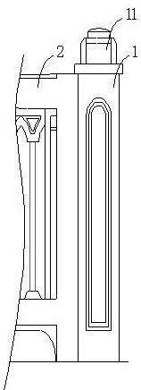
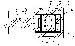
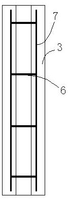
[0073] For specific implementation: see Figure 1-4 , a concrete railing column at the end of a bridge road for cast-in-place construction, including a column body 1, the lower end of which is fixed to the column installation positions at the outer edges of the road ends on both sides of the upper surface of the bridge, and the column body faces the side of the bridge A baffle 2 is fixedly arranged, and a column head 11 is also provided at the upper end of the column, wherein the column includes a vertically arranged panel part 3, and the panel part 3 has three outer sides and is used to form the front and rear sides and the front and rear sides of the column. On the side of the terminal, the inside of the panel has a cavity that opens away from the side of the terminal. The end of the baffle is sandwiched at the opening of the cavity and encloses a pouring space ...


PUM


Abstract

The invention discloses a concrete railing column at the end of a bridge road for cast-in-place construction, which includes a column body, the lower end of which is fixed to the column installation positions on the outer edges of the road ends on both sides of the upper surface of the bridge, and the column body faces one side of the bridge. The side is fixed with a baffle, and the upper end of the column is also provided with a column head. It is characterized in that the column includes a vertically arranged panel, and the panel has three outer sides and is used to form the front and rear sides and ends of the column. On the side of the head, the inside of the panel has a cavity that opens away from the side of the end. The end of the baffle is sandwiched at the opening of the cavity and encloses a pouring space with the panel. The pouring space is provided with a concrete interior The core and rely on the concrete core to fix the panel parts and the end of the slab as a whole. The invention has the advantages of being convenient for prefabrication and transportation, improving the convenience of on-site construction, improving the construction quality and the strength of the installed railings, and the like.

Description

technical field [0001] The invention relates to the technical field of bridge railings, in particular to a concrete railing column at the end of a bridge road constructed in-situ. Background technique [0002] Usually, during bridge construction, sidewalks will be set on both sides of the bridge, and bridge railings will be set on the outer edges of the sidewalks to protect pedestrians from falling under the bridge. There are usually wooden structure railings, metal structure railings and concrete structure railings for bridge railings. Among them, concrete structure railings are widely used because of their firm structure, convenient construction, and low cost. The railing of the concrete structure is composed of a plurality of railing columns arranged at intervals, and a railing plate connected between the railing columns, wherein the railing column is a basic component for support. [0003] The existing bridge road concrete railing column structure usually includes a co...

Claims


Application Information

Patent Timeline
Patent Type & Authority Patents(China)
IPC IPC(8): E01D19/10E01D21/00B28B7/30B28B7/34B28B7/16B28B7/00
CPCE01D19/103E01D21/00B28B7/30B28B7/348B28B7/16B28B7/0002
Inventor 杨浩
Owner 重庆长赛新材料科技有限公司
Learn More