
Cast-in-place pile reinforcement cage lowering device

A technology for steel cages and cast-in-place piles, which is applied in construction, infrastructure engineering and other directions, can solve the problems of inability to adjust and fix steel cages, affect construction efficiency, dangerous accidents, etc. Effects of dangerous accidents

Active Publication Date: 2020-11-13
嘉兴鼎尚信息科技有限公司
View PDF8 Cites 3 Cited by
  • Summary
  • Abstract
  • Description
  • Claims
  • Application Information

AI Technical Summary

Problems solved by technology

[0003] For the work below the existing reinforcement cage, it is usually completed by hoisting with a crane. For the work of hoisting the reinforcement cage below, on the one hand, when working under the reinforcement cage in the prior art, the connection and fixation stability and firmness of the reinforcement cage are not enough. , when working below, it may loosen and cause dangerous accidents. On the other hand, when hoisting the lower device, it cannot be adjusted and fixed according to the cage diameter of the steel cage and the size of the steel bar, and thus the construction cannot be carried out according to the actual construction situation. , causing inconvenience to the bottom of the steel cage, affecting the construction efficiency, delaying the construction progress, and further affecting the economic benefits of the construction work. For this reason, the present invention proposes a cast-in-situ pile reinforcement cage lowering device to solve the above problems

Method used


Image

  • Cast-in-place pile reinforcement cage lowering device
  • Cast-in-place pile reinforcement cage lowering device
  • Cast-in-place pile reinforcement cage lowering device

Examples


Embodiment Construction

[0028] The technical solutions in the embodiments of the present invention will be clearly and completely described below. The embodiments of the present invention and all other embodiments obtained by persons of ordinary skill in the art without making creative efforts belong to the protection scope of the present invention.

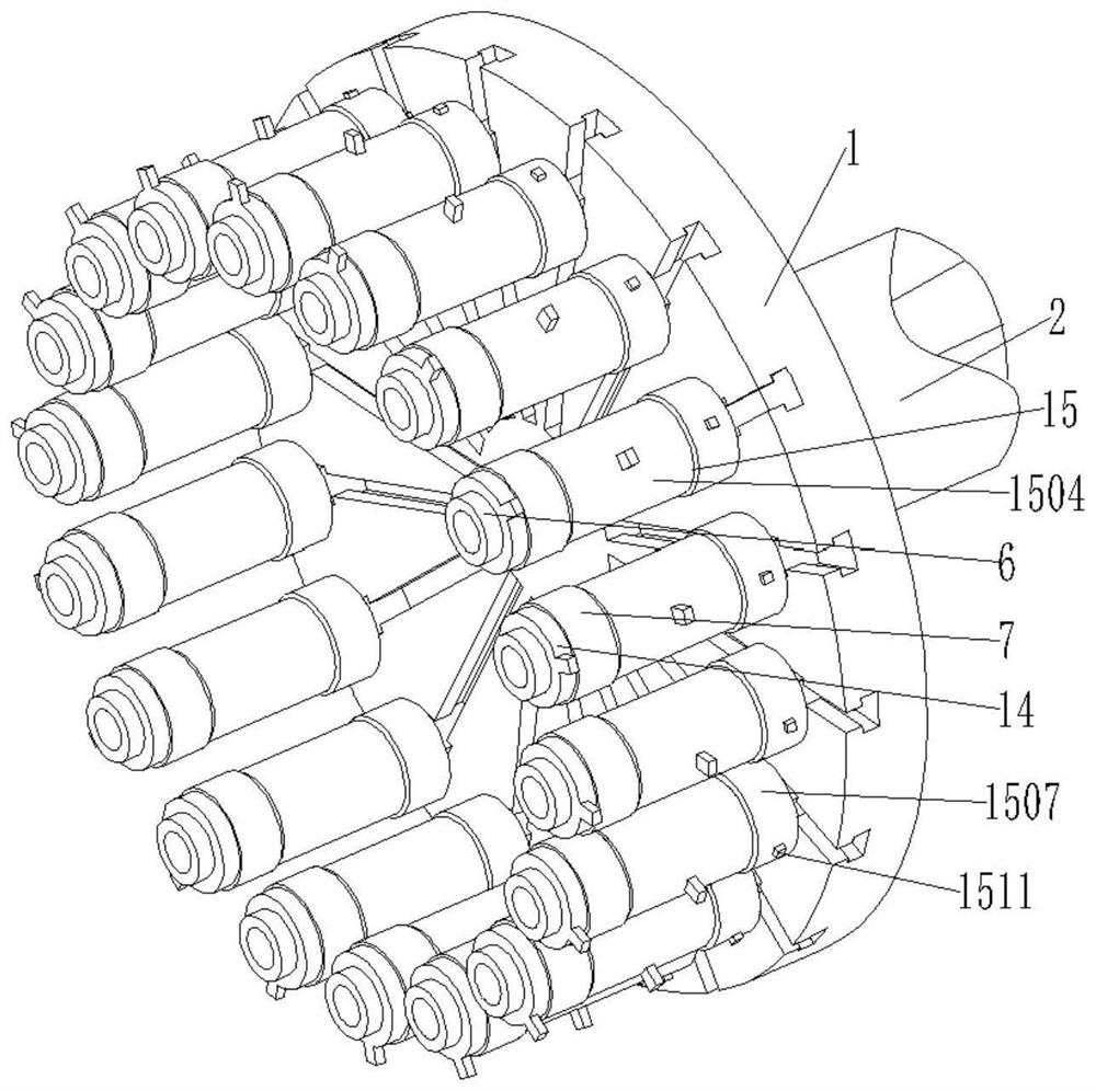
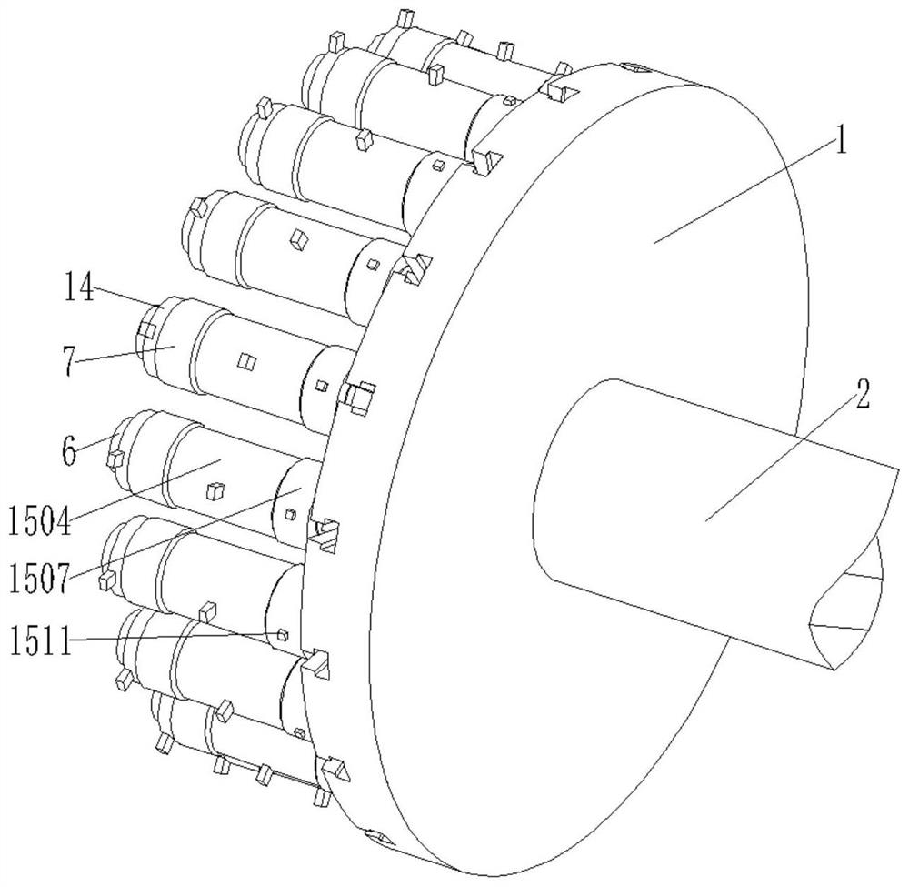
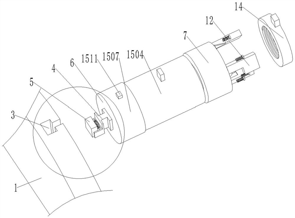
[0029] see figure see Figure 1 to Figure 9 , the present invention provides a technical solution: a cast-in-situ pile reinforcement cage lowering device, including a hanging pan 1, a boom 2, a placement pipe 6 and a strengthening and fixing mechanism 15;

[0030] The hanging pan 1 is integrally formed on the suspender 2, and the hanging pan 1 is equidistantly provided with convex chutes 3, and the sliding connection of the convex chute 3 is provided with a convex slider 4;

[0031] A groove is arranged in the convex slider 4, and a movable extruding block 5 is movably connected in the groove, and one end of the movable extruding block 5 is connected w...


PUM


Abstract

The invention discloses a cast-in-place pile reinforcement cage lowering device. During lowering construction of a cast-in-place pile reinforcement cage, convex sliding grooves equidistantly formed ina hanging disk are slidably connected with convex sliding blocks to drive placing tubes to change the positions. As for fixing of a reinforcement cage during lowering operation, the reinforcement cage can be fixed and placed correspondingly according to the diameter of different cage bodies of the reinforcement cage and the diameters of steel bars, and then the reinforcement cage can be lowered according to the actual situation. The working efficiency is improved. The engineering construction progress is accelerated. The work economic benefits are increased. Reinforcing and fixing mechanismsare arranged on the placing tubes and can improve the placing and fixing firmness and the connecting strength of the reinforcement cage during lowering operation of the reinforcement cage. The stability of the reinforcement cage in the lowering operation process is ensured. Occurrence of accidents is avoided.

Description

technical field [0001] The invention relates to the technical field of building construction equipment, in particular to a lowering device for cast-in-place pile reinforcement cages. Background technique [0002] With the rapid development of my country's construction projects, especially high-rise buildings, the processing of foundations, my country's construction projects have begun to use the concrete pouring pile foundation technology in bridge construction; There are various forms, but cast-in-situ piles are widely used in the construction of high-rise buildings on soft foundations; at the same time, due to construction period and cost reasons, construction units often require pile foundations to be started without excavation of the earthwork on site. Construction. During the construction process, cast-in-situ piles are widely used in construction due to their advantages of no vibration, no soil extrusion, low noise, and suitable for use in densely built urban areas durin...

Claims


Application Information

Patent Timeline
Patent Type & Authority Applications(China)
IPC IPC(8): E02D15/08
CPCE02D15/08
Inventor 王属俊
Owner 嘉兴鼎尚信息科技有限公司
Learn More