
Fingerprint lock with finger cleaning function

A fingerprint lock and cleaning technology, applied in the field of fingerprint locks, can solve the problems that affect the identification use, the fingerprint lock cannot be recognized, the residual water on the touchpad, etc., to achieve the effect of less time and improved recognition rate

Inactive Publication Date: 2020-11-13
李永杰
View PDF8 Cites 2 Cited by
  • Summary
  • Abstract
  • Description
  • Claims
  • Application Information

AI Technical Summary

Problems solved by technology

[0003] However, when the current fingerprint lock is used in daily use, especially in the office, the entry and exit are relatively frequent. After washing hands in the public toilet and entering the company, there will often be a problem that the fingerprint lock cannot be recognized due to the residual water on the finger, and it will also make the fingerprint lock unrecognizable. Residual water on the touch panel will affect the subsequent identification and use

Method used


Image

  • Fingerprint lock with finger cleaning function
  • Fingerprint lock with finger cleaning function
  • Fingerprint lock with finger cleaning function

Examples


Embodiment 1

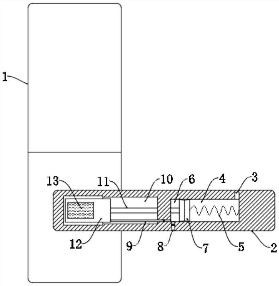
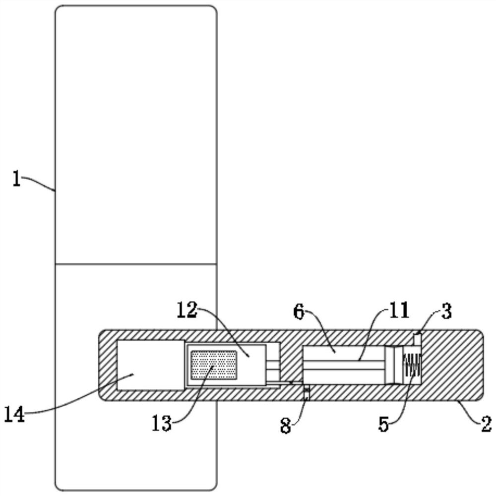
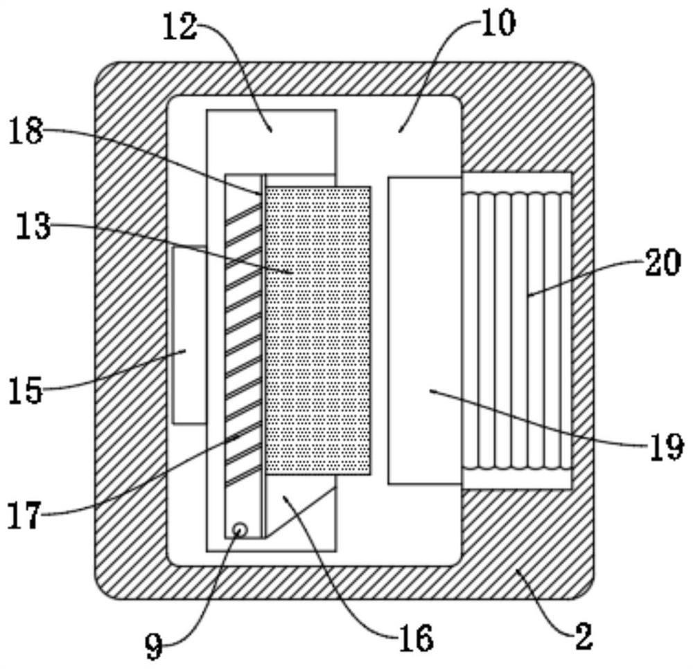
[0020] refer to Figure 1-3 , a fingerprint lock with finger cleaning function, comprising a fingerprint lock body 1 and a lock handle 2, the touch panel 14 of the fingerprint lock body 1 is arranged on the left side of the lock handle 2, and the lock handle 2 is provided with cleaning grooves from left to right 10 and a cylindrical cavity, a piston 7 is arranged in the cylindrical cavity, and the piston 7 divides the cylindrical cavity into a first cavity 6 and a second cavity 4. The front side of the touch panel 14 is provided with an elastic plate 12, and the elastic plate 12 A sump 16 is provided on the front of the sump 16, and a squeeze net 18 is fixed on the inner wall of the sump 16. A plurality of water guide rods 17 are connected between the back side of the water squeeze net 18 and the inner bottom of the sump 16, and the water guide rods 17 are inclined downward. , a plurality of inclined water guide rods 17 are provided, so that the water on the squeeze net 18 can...

Embodiment 2

[0025] refer to Figure 4 The difference between this embodiment and Embodiment 1 is that an electromagnet 21 is embedded in the flushing plate 19, the flushing net 18 and the flushing plate 19 are made of stainless steel, and one end of the electromagnet 21 is connected to the flushing plate 19 The two ends of the coil wound on the electromagnet 21 are electrically connected with the piezoelectric ceramic sheet 15 .

[0026] In the process of fingers initially squeezing the elastic plate 12, the piezoelectric ceramic sheet 15 supplies power for the first time, and when the water-squeezing plate 19 squeezes the water-absorbing sponge 13, the elastic plate 12 is also squeezed for the second time. Extruding the piezoelectric ceramic sheet 15 for the second time, the electric energy partly supplied for the first time to the electromagnet 21, and the electric energy fully supplied to the electromagnet 21 for the second time, and the electromagnet 21 makes the water squeezing plate...


PUM


Abstract

The invention discloses a fingerprint lock with a finger cleaning function. The fingerprint lock with the finger cleaning function comprises a fingerprint lock body and a lock handle, a touch plate ofthe fingerprint lock body is arranged on the left side of the lock handle, a cleaning groove and a cylindrical cavity are sequentially formed in the lock handle from left to right, a piston is arranged in the cylindrical cavity, and the cylindrical cavity is divided into a first cavity body and a second cavity body through the piston; an elastic plate is arranged on the front side of the touch plate, a water collecting groove is formed in the front face of the elastic plate, a water squeezing net is fixed to the inner wall of the water collecting groove, and water absorption sponge is bondedto the outer wall of the water squeezing net; and a piezoelectric ceramic piece is installed on the back face of the touch plate, a connecting rod extending into the cleaning groove is fixed to the left side of the piston, the tail end of the connecting rod is fixed to an elastic plate, and the right side of the piston is elastically connected with the inner wall of the cylindrical cavity througha spring. The fingerprint lock is reasonable in structure, fingers can be rapidly cleaned before recognition every time, and the recognition rate is increased.

Description

technical field [0001] The invention relates to the technical field of fingerprint locks, in particular to a fingerprint lock with a finger cleaning function. Background technique [0002] Fingerprint locks are intelligent locks, which are the perfect crystallization of computer information technology, electronic technology, mechanical technology and modern hardware technology. The characteristics of fingerprints have become the most important evidence for identification and are widely used in public security criminal investigation and judicial fields. [0003] However, when the current fingerprint lock is used in daily use, especially in the office, the entry and exit are relatively frequent. After washing hands in the public toilet and entering the company, there will often be a problem that the fingerprint lock cannot be recognized due to the residual water on the finger, and it will also make the fingerprint lock unrecognizable. Residual water on the touchpad will affec...

Claims


Application Information

Patent Timeline
Patent Type & Authority Applications(China)
IPC IPC(8): E05B17/00G07C9/00
CPCE05B17/00G07C9/00563
Inventor 李永杰黄倩
Owner 李永杰
Learn More