Multi-surface-supporting welded exhaust hood of industrial steam turbine

An industrial steam turbine and steam exhaust cylinder technology, which is applied in the field of steam turbine exhaust cylinders, can solve problems such as increased vibration of the rotating shaft, deformation of the joint of the blade rotating shaft, and reduced safety and stability of the steam turbine, achieving the goal of reducing vibration and improving safety and stability Effect

Active Publication Date: 2020-11-13
HANGZHOU STEAM TURBINE
View PDF13 Cites 1 Cited by
  • Summary
  • Abstract
  • Description
  • Claims
  • Application Information

AI Technical Summary

Problems solved by technology

Existing welded exhaust cylinders with blade shaft connections are generally supported horizontally on the left and right sides. However, during the actual operation of the unit, the blade shaft connections will be significantly deformed, resulting in increased vibration of the shaft and reduced safety and stability of the steam turbine. , which is more obvious on large and super large exhaust cylinders

Method used


Image

  • Multi-surface-supporting welded exhaust hood of industrial steam turbine
  • Multi-surface-supporting welded exhaust hood of industrial steam turbine
  • Multi-surface-supporting welded exhaust hood of industrial steam turbine

Examples


Embodiment 1

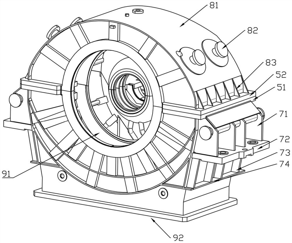
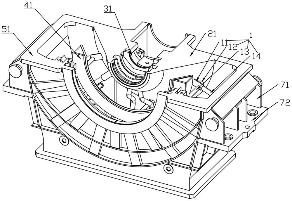
[0024] like figure 1 , 3 As shown, a welded exhaust cylinder of an industrial steam turbine supported by multiple surfaces includes an upper part of the exhaust cylinder and a lower part of the exhaust cylinder. A rod support assembly 1 is fixed on the diffuser inner guide ring 21. The rod support assembly 1 includes a sleeve rod 11, a first cross bar 14, a second cross bar 13 and an abutment plate 12. One end of the sleeve rod 11 is connected to the diffuser. The arc side of the inner guide ring 21 is fixedly connected, the other end of the sleeve rod 11 is connected to one end of the first cross bar 14, and the end of the first cross bar 14 not connected to the sleeve rod 11 is fixedly connected to the inner side wall of the lower part of the exhaust cylinder. One end of the second cross bar 13 is fixedly connected to the arc side of the sleeve rod 11, the other end of the second cross bar 13 is fixedly connected to the inner front wall of the lower part of the exhaust cyli...

Embodiment 2

[0030] The center of circle of the lower bottom surface of the diffuser inner guide ring 21 is set as the origin, and the ray where the diameter of the lower bottom surface of the diffuser inner guide ring 21 is parallel to the horizontal line is set as the x-axis, and the inner guide ring 21 of the diffuser is The ray where the diameter of the lower bottom surface is perpendicular to the x-axis is set as the y-axis, the ray where the central axis of the diffuser inner guide ring 21 is located is set as the z-axis, and the first crossbar 14 is respectively connected to the x-axis, y-axis and z-axis The acute angles formed are 20°~30°, 70°~80° and 65°~75°; the acute angles formed by the second cross bar 13 with the x-axis, y-axis and z-axis respectively are 85°-90°, 0 °~5° and 85°~90°. The direction in which the connecting part of the sleeve rod 11 and the diffuser inner guide ring 21 receives the force from the connecting part of the blade shaft is the tangential direction of ...

Embodiment 3

[0032] The sleeve rod 11 is provided with a first mass chamber, the first mass chamber is filled with liquid, one end of the first cross bar 14 is set in the first mass chamber and has an interference fit with the first mass chamber, and the lower part of the exhaust cylinder A second mass cavity is provided in the front wall, and one end of the second crossbar 13 is disposed in the second mass cavity and is interference fit with the second mass cavity. When the exhaust steam displacement is large, the temperature of the exhaust cylinder rises, and the liquid in the first volume chamber expands. The first cross bar 14 no longer can only passively provide support force, but can also actively provide support for the lower exhaust cylinder. The driving force further reduces the deformation of the connecting part of the blade shaft. Similarly, the liquid in the second volume cavity also expands, and the second crossbar 13 provides supporting force and driving force for the first c...


PUM


Abstract

The invention discloses a multi-surface-supporting welded exhaust hood of an industrial steam turbine. The welded exhaust hood comprises an exhaust hood upper part and an exhaust hood lower part. A rod supporting assembly is fixedly arranged on a diffusion inner flow guide ring and comprises a sleeve rod, a first transverse rod, a second transverse rod and an abutting plate, one end of the sleeverod is fixedly connected with the arc side face of the diffusion inner flow guide ring, the other end of the sleeve rod is connected with one end of the first transverse rod, the end, not connected with the sleeve rod, of the first transverse rod is fixedly connected with the inner side wall of the exhaust hood lower part, one end of the second transverse rod is fixedly connected with the arc sideface of the sleeve rod, and the other end of the second transverse rod is fixedly connected with the inner front wall of the exhaust hood lower part. Horizontal supporting plates are arranged on theouter rear wall and the two outer side walls of the exhaust hood lower part, horizontal reinforcing plates are arranged on the outer front wall, the outer rear wall and the two outer side walls of theexhaust hood lower part, a plurality of first vertical reinforcing plates are arranged between a lower flange and the horizontal supporting plates, and a plurality of second vertical reinforcing plates are arranged between the horizontal supporting plates and the horizontal reinforcing plates.

Description

technical field [0001] The invention relates to the technical field of exhaust cylinders of steam turbines, in particular to a welded exhaust cylinder of industrial steam turbines supported by multiple surfaces. Background technique [0002] Conventional condensing steam turbine units are provided with a single exhaust cylinder. The steam exhaust cylinder comprises an upper part of the steam exhaust cylinder and a lower part of the steam exhaust cylinder, the upper part of the steam exhaust cylinder is provided with an upper flange, and the lower part of the steam exhaust cylinder is provided with a lower flange. The lower steam inlet is provided on the front wall of the lower part of the cylinder, the bottom wall opening of the lower part of the steam exhaust cylinder is set to form a steam exhaust port, the inner rear wall of the lower part of the exhaust cylinder is provided with a diffuser inner guide ring, and the diffuser inner The guide ring is in the shape of a semi...

Claims


Application Information

Patent Timeline
Patent Type & Authority Applications(China)
IPC IPC(8): F01D25/30F01D25/28
CPCF01D25/30F01D25/28
Inventor 张科杨雄民张超陆晋刘盼年来鸿魏波高强米海波陈哲彬卢红远潘超锋吴涛
Owner HANGZHOU STEAM TURBINE
Why Eureka
Try Eureka