Projection screen and projection system

A technology of projection screen and cylindrical microlens, which is applied in the field of projection display, can solve the problems of uneven image intensity and uneven distribution of light intensity displayed on the projection screen, and achieve the effect of improving the uniform effect of display brightness

Active Publication Date: 2020-11-13
CHENGDU FSCREEN SCI TECH
View PDF22 Cites 2 Cited by
  • Summary
  • Abstract
  • Description
  • Claims
  • Application Information

AI Technical Summary

Problems solved by technology

[0004] In view of this, the purpose of the present invention is to provide a projection screen to solve the problem of uneven intensity of images displayed on the projection screen caused by the uneven distribution of light intensity of the light source in the existing projection screen

Method used


Image

  • Projection screen and projection system
  • Projection screen and projection system
  • Projection screen and projection system

Examples


Embodiment 1

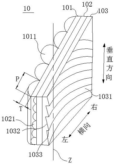
[0049] Such as figure 2 As shown, a projection screen includes a columnar microlens layer 101 arranged along the thickness direction of the projection screen, a first substrate layer 102 and a reflective microstructure layer 103, and the columnar microlens layer 101 is arranged on one side of the first substrate layer 102 side. Wherein, the columnar microlens layer 101 includes a columnar microlens layer I and a columnar microlens layer II, and the columnar microlens layer I includes a plurality of vertical columnar microlenses 1011, with the central axis Z as the reference, along the horizontal direction of the projection screen toward both ends. The aspect ratio of the set vertical columnar microlenses 1011 decreases gradually, and the central axis Z is the symmetry axis of the vertical columnar microlenses 1011 whose aspect ratio is the maximum in the columnar microlens layer I; the columnar microlens layer II includes several transverse The columnar microlenses 1021 , th...

Embodiment 2

[0082] On the basis of Example 1, as Figure 10 As shown, diffusing particles and / or light-absorbing materials are arranged on the columnar microlens layer.

[0083] Such as Figure 10 As shown in a, the columnar microlens layer includes a columnar microlens layer I composed of several vertical columnar microlenses 1011 and a columnar microlens layer II composed of several horizontal columnar microlenses 1021, wherein the vertical columnar microlenses 1011 and the horizontal columnar microlenses Diffusion particles 1034 are arranged in the microlenses 1021, and these diffusion particles 1034 can uniformly scatter the light passing through the columnar microlens layer, further making the light intensity distribution more uniform. Diffusion particles 1034 include but are not limited to silicon dioxide particles, aluminum oxide particles, titanium oxide particles, cerium oxide particles, zirconium oxide particles, tantalum oxide particles, zinc oxide particles, magnesium fluorid...

Embodiment 3

[0091] The difference between this embodiment and the projection screen of Embodiment 1 is that: refer to Figure 11 As shown in the schematic diagram of the structure of the projection screen, the surface of the columnar microlens layer 101 away from the first substrate layer 102 is a rough surface 1012, and the rough surface 1012 is in the vertical direction of the columnar microlens layer 101. The cylindrical surface of the cylindrical microlens 1011 is formed by roughening. Here, the rough surface 1012 may be formed by sandblasting or surface roughening of the mold, followed by transfer printing with glue or spraying glue with diffused particles. The rough surface 1012 can further diffuse the light, and play the role of uniform light, hardening protection and imaging.


PUM


Abstract

The invention provides a projection screen and a projection system, and belongs to the field of projection display. The projection screen comprises a columnar micro-lens layer, a first base material layer and a reflection microstructure layer which are arranged in the thickness direction of the projection screen, and the columnar micro-lens layer comprises a columnar micro-lens layer I and a columnar micro-lens layer II and is arranged on one side of the first base material layer; the columnar micro-lens layer I comprises a plurality of vertical columnar micro-lenses, and the height-width ratio of the vertical columnar micro-lenses arranged in the direction from the transverse direction of the projection screen to the two ends is gradually reduced by taking the central axis as a reference;the columnar micro-lens layer II comprises a plurality of transverse columnar micro-lenses, and the height-width ratio of the transverse columnar micro-lenses is gradually reduced from one side to the other side in the vertical direction of the projection screen; the reflection microstructure layer is provided with a plurality of microstructures, and the microstructures are arc-shaped or parabola-shaped or oval or linear. The projection system comprises a projector and the projection screen. According to the invention, the brightness uniformity of the projection screen and the projection system is improved.

Description

technical field [0001] The invention belongs to the technical field of projection display, and in particular relates to a projection screen and a projection system. Background technique [0002] Projection display requires a projector and a projection screen. The function of the projection screen is to image the image emitted by the projector and redistribute the projection light intensity. The fine structure diffuses and converges the projected light or controls the transmission direction of the light as needed to meet the needs of different viewing fields. The current widespread problem with projection screens is that the brightness displayed on the screen varies greatly in different viewing positions. Unlike LCD or LED screens, there will not be a large difference in display brightness within a large field of view, so projection One of the gaps between the screen and LCD or LED is that under different viewing fields of view on the projection screen, the viewer feels unev...

Claims


Application Information

Patent Timeline
Patent Type & Authority Applications(China)
IPC IPC(8): G03B21/602G03B21/60
CPCG03B21/60G03B21/602
Inventor 王起飞张益民罗坚
Owner CHENGDU FSCREEN SCI TECH
Why Eureka
Try Eureka