
Backlight module and display device

A backlight module and display panel technology, which is applied in optics, nonlinear optics, instruments, etc., can solve the problems of chips easily forming shadows and low brightness around them, and achieve the effects of reducing the probability of shadows and increasing brightness

Pending Publication Date: 2021-07-27
TCL CHINA STAR OPTOELECTRONICS TECH CO LTD
View PDF7 Cites 0 Cited by
  • Summary
  • Abstract
  • Description
  • Claims
  • Application Information

AI Technical Summary

Problems solved by technology

[0005] An embodiment of the present invention provides a backlight module and a display device to solve the problem that in the existing backlight module and display device, the central brightness of the light emitted by the LED chip is relatively high, and the surrounding brightness is low, resulting in a gap between two adjacent LED chips. Technical issues prone to shadow formation

Method used


Image

  • Backlight module and display device
  • Backlight module and display device
  • Backlight module and display device

Examples


Embodiment Construction

[0037] The following will clearly and completely describe the technical solutions in the embodiments of the present invention with reference to the accompanying drawings in the embodiments of the present invention. Obviously, the described embodiments are only some, not all, embodiments of the present invention. Based on the embodiments of the present invention, all other embodiments obtained by those skilled in the art without creative efforts fall within the protection scope of the present invention. In addition, it should be understood that the specific embodiments described here are only used to illustrate and explain the present invention, and are not intended to limit the present invention. In the present invention, unless stated to the contrary, the used orientation words such as "up" and "down" usually refer to up and down in the actual use or working state of the device, specifically the direction of the drawing in the drawings ; while "inside" and "outside" refer to ...


PUM


Abstract

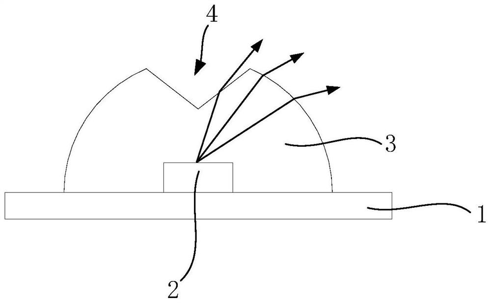
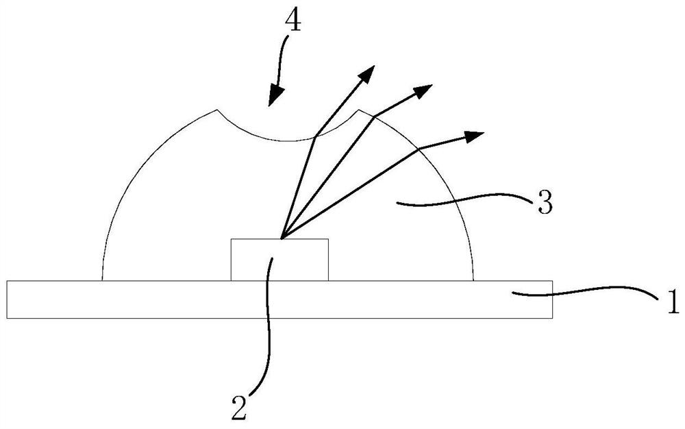
The invention discloses a backlight module and a display device, the backlight module comprises a substrate, a plurality of LED chips and a sealing glue layer, the plurality of LED chips are arranged on the substrate at intervals, and the sealing glue layer is arranged on the substrate and covers the plurality of LED chips; one side, far away from the LED chips, of the sealing glue layer is provided with a plurality of concave parts, and the plurality of concave parts are arranged above the plurality of LED chips and are in one-to-one correspondence with the plurality of LED chips, so that light right above the LED chips is opened towards the periphery, side surface light emitting of the LED chips is increased, the brightness of an area between two adjacent LED chips is increased, and the probability of shadow generation is reduced.

Description

technical field [0001] The invention relates to the field of display technology, in particular to a backlight module and a display device. Background technique [0002] Compared with traditional backlights, Mini light-emitting diode (Mini LED) backlights have the characteristics of ultra-thin, high brightness, and multi-segmentation. Therefore, the industry usually uses Mini LEDs as backlights for liquid crystal displays. [0003] The size and pitch of the Mini-LED, as well as the required optical distance (OD) are the key parameters determining the thickness and cost of the whole machine. When the product adopts a thin design, the OD requirements for the backlight also need to be It is getting higher and higher, that is, a smaller OD is required to meet the demand. However, limited by the light-emitting angle and light-emitting uniformity of the LED chip, the OD cannot be further reduced. When the OD is kept to a minimum, since the light emitted by the LED chip is concentr...

Claims


Application Information

Patent Timeline
IPC IPC(8): G02F1/13357
CPCG02F1/133606G02F1/133611G02F1/133603H01L33/54H01L25/0753H01L33/20
Inventor 程希
Owner TCL CHINA STAR OPTOELECTRONICS TECH CO LTD
Learn More