
Potentiometer with pressing self-locking switch

A self-locking switch and potentiometer technology, applied in the field of potentiometers, can solve the problems that the knob cannot be used, hinder the operation of the equipment, occupy a large space, etc., and achieve the effect of reducing the installation space, facilitating the operation of the equipment, and avoiding the cumbersome wiring.

Pending Publication Date: 2020-11-13
CHENGDU HONGMING ELECTRONICS CO LTD
View PDF0 Cites 0 Cited by
  • Summary
  • Abstract
  • Description
  • Claims
  • Application Information

AI Technical Summary

Problems solved by technology

[0004] First, the connection between the potentiometer part and the switch part is relatively fixed, and the work between the two is prone to interference and failure, and the electrical and mechanical performance of the potentiometer part and the switch part can only be tested after the entire product is assembled. , the process quality control is difficult, the product qualification rate is low, and the product reliability is low, so it is not suitable for equipment with high reliability requirements
[0005] Second, the wiring terminals of the potentiometer part and the switch part are welded by wire. Each potentiometer with a push self-locking switch needs to weld 5 wires, 3 wires on the potentiometer, and 2 wires on the switch. The wires occupy the equipment. The external space is large, the wiring is cumbersome, and electrical equipment failures such as wrong connection and missing wiring are prone to occur, and troubleshooting is difficult, which is not conducive to meeting the requirements of equipment miniaturization, standardization and reliability, and hinders the application of large quantities of potentiometers on small equipment; In addition, the sleeve type installation method will also occupy a large space, which is not conducive to the application of large quantities of potentiometers on small devices
[0006] Third, the screw fastening structure is used between the metal shaft and the knob. The knob cannot be made of transparent materials such as glass, and cannot realize the light guiding function. Therefore, it is impossible to quickly and accurately identify the position of the potentiometer on the device in an environment with insufficient light. The working mode hinders the operation of the equipment and limits the application of the potentiometer on the equipment in this field

Method used


Image

  • Potentiometer with pressing self-locking switch
  • Potentiometer with pressing self-locking switch
  • Potentiometer with pressing self-locking switch

Examples


Embodiment Construction

[0034] The present invention will be further described below in conjunction with accompanying drawing:

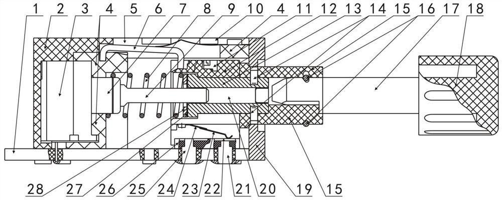
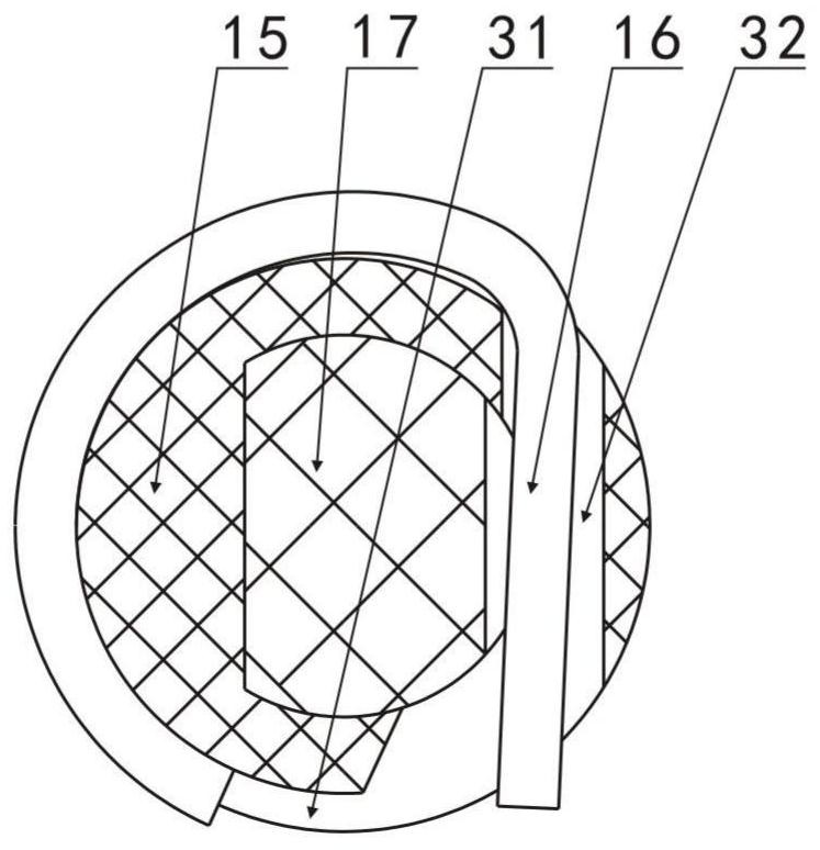
[0035] Such as figure 1 and figure 2 As shown, the potentiometer with push self-locking switch of the present invention includes an outer shell 4, a potentiometer part 3 and a switch part, and the potentiometer part 3 is installed on the front part of the outer shell 4, and the potentiometer part 3 includes a shaft sleeve 7 And the rotating shaft 9 installed on the shaft sleeve 7, the rotating shaft 9 is used to drive the brush in the potentiometer part 3 (see Figure 6 The brush 38) rotates, and the switch part includes a positioning rod 6, a slide block 12, a knob shaft 17 and a knob handle 18, and the outer wall of the outer casing 4 is provided with a groove 5, and the outer casing 4 is provided with a through hole (Fig. unmarked), there is a communication channel between the groove 5 of the outer shell 4 and the through hole (not marked in the figure), the two ends ...


PUM


Abstract

The invention discloses a potentiometer with a pressing self-locking switch. The potentiometer comprises an outer shell, a potentiometer component and a switch component, wherein the potentiometer component comprises a shaft sleeve and a rotating shaft installed on the shaft sleeve; the switch component comprises a positioning rod, a sliding block, a knob shaft, a knob handle, a compressed spring,a transmission sleeve, a connecting sleeve and a conductive on-off device; the sliding block is provided with a through hole, the transmission sleeve is installed in the through hole, the sliding block and the transmission sleeve can rotate relatively and cannot move front and back relatively, the transmission sleeve is provided with a center through hole, the rotating shaft is arranged in the center through hole, the compressed spring is located between the transmission sleeve and the hole wall of the front portion of the through hole of the outer shell, the transmission sleeve is connectedwith the connecting sleeve, and the knob shaft is connected with the connecting sleeve. According to the invention, a potentiometer function and a switch function can be achieved, the two functions donot influence each other, independent machining, independent testing and rapid assembling of the potentiometer component and the switch component are facilitated, the quality is convenient to control, the product percent of pass is high, the product reliability is high, and the potentiometer is suitable for equipment with high reliability requirements.

Description

technical field [0001] The invention relates to a potentiometer with a switch mainly used in a circuit or equipment, in particular to a potentiometer with a push self-locking switch. Background technique [0002] The potentiometer with switch has both on and off functions and potentiometer function, that is, voltage adjustment or resistance detection function. It is mainly used for switching power supply control and voltage control in circuits or equipment. Its working mode is divided into work when the switch is disconnected and switch connection. There are two kinds of working modes. In these two working modes, the function of the potentiometer, that is, the function of voltage regulation or resistance detection, is not affected. In order to facilitate switching operation, push self-locking switches are generally used. The corresponding potentiometer is generally called a potentiometer with push self-locking switch. Its basic structure includes the outer shell, potentiomet...

Claims


Application Information

Patent Timeline
IPC IPC(8): H01C10/36H01C1/16H01C1/04H01C1/01
CPCH01C1/01H01C1/04H01C1/16H01C10/36
Inventor 彭键刘珍杨水兵康太宇欧阳勇李忠林谭爽吴永胜杨飞周园园姚里
Owner CHENGDU HONGMING ELECTRONICS CO LTD
Learn More