Supercharge Your Innovation With Domain-Expert AI Agents!

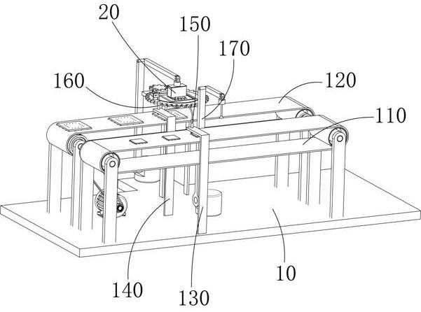
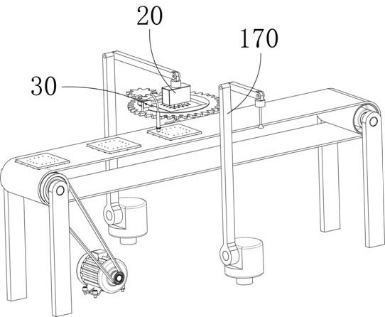
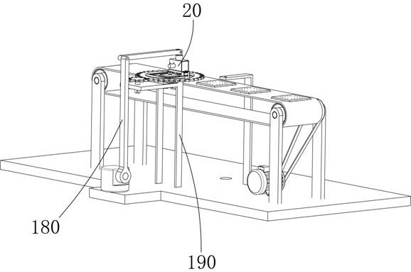
A chip packaging manufacturing equipment

A technology for manufacturing equipment and chip packaging, which is applied in semiconductor/solid-state device manufacturing, transportation and packaging, electrical components, etc. It can solve problems such as increased bonding energy, lead deformation, chip lead position deviation, etc., to improve packaging manufacturing efficiency, Avoid the effect of moving

Inactive Publication Date: 2021-05-04
深圳市三航工业技术研究院
View PDF14 Cites 2 Cited by
  • Summary
  • Abstract
  • Description
  • Claims
  • Application Information

AI Technical Summary

Problems solved by technology

Chips need to be wire-bonded during chip packaging. The new bonding equipment can automatically extend the bonding time and increase the bonding energy, so that the contaminated surface can be bonded by friction to form a large enough adhesive force. Lead deformation to a large extent and frequent lead breakage at the root of the bond
During the wiring process, the chip is easy to move, causing the position deviation of the chip lead

Method used


Image

  • A chip packaging manufacturing equipment
  • A chip packaging manufacturing equipment
  • A chip packaging manufacturing equipment

Examples


Embodiment Construction

[0028] The technical solutions of the present invention will be further described below in conjunction with the accompanying drawings and through specific implementation methods.

[0029] Wherein, the accompanying drawings are only for illustrative purposes, showing only schematic diagrams, rather than physical drawings, and should not be construed as limitations on this patent; in order to better illustrate the embodiments of the present invention, some parts of the accompanying drawings will be omitted, Enlargement or reduction does not represent the size of the actual product; for those skilled in the art, it is understandable that certain known structures and their descriptions in the drawings may be omitted.

[0030] In the drawings of the embodiments of the present invention, the same or similar symbols correspond to the same or similar components; , "inner", "outer" and other indicated orientations or positional relationships are based on the orientations or positional ...


PUM


Abstract

The invention discloses a chip packaging manufacturing equipment, which includes a base, a conveyor belt 1, and a conveyor belt 2. The conveyor belt 1 and conveyor belt 2 are installed on the base, and the conveyor belt 1 and conveyor belt 2 are arranged in parallel. Conveyor belt 1 is used to transport the initial chips, and conveyor belt 2 is used to transport the chips after processing. A suction manipulator is arranged between the conveyor belt 1 and the conveyor belt 2, and the suction manipulator can absorb the chips. One side of the conveyor belt 2 is provided with a welding manipulator, and the suction manipulator grabs the initial chip into the limiting groove on the turntable, and then the welding assembly welds the chip. When the chip is placed in the limiting groove, the welding assembly The welding gun welds the leads to the chip, the motor drives the toothed plate to rotate, and then drives the toothed plate to rotate, thereby driving the turntable to rotate, so as to rotate the chip and weld the leads to improve the packaging and manufacturing efficiency of the chip.

Description

technical field [0001] The invention relates to the technical field of chip packaging, in particular to a chip packaging manufacturing equipment. Background technique [0002] Chip, also known as microcircuit, microchip, integrated circuit. Refers to silicon chips containing integrated circuits, which are small in size and are often part of computers or other electronic equipment. Chips need to be wire-bonded during chip packaging. The new bonding equipment can automatically extend the bonding time and increase the bonding energy, so that the contaminated surface can be bonded by friction to form a large enough adhesive force. It causes deformation of the wire to a large extent and frequently causes wire breakage at the root of the bond. During the wiring process, the chip is prone to move, resulting in deviation of the lead position of the chip. Contents of the invention [0003] In order to solve the deficiencies of the prior art, the object of the present invention i...

Claims


Application Information

Patent Timeline
Patent Type & Authority Patents(China)
IPC IPC(8): H01L21/67H01L21/677
CPCH01L21/67121H01L21/67706
Inventor 朱雪峰
Owner 深圳市三航工业技术研究院
Features
  • R&D
  • Intellectual Property
  • Life Sciences
  • Materials
  • Tech Scout
  • Unparalleled Data Quality
  • Higher Quality Content
  • 60% Fewer Hallucinations
Learn More