
K-band phased array element corner cutting and arraying method

A phased array antenna and phase-controlled technology, applied in electrical components, antennas, etc., to save costs and improve side lobe suppression

Active Publication Date: 2020-11-13
NO 63921 UNIT OF PLA
View PDF8 Cites 0 Cited by
  • Summary
  • Abstract
  • Description
  • Claims
  • Application Information

AI Technical Summary

Problems solved by technology

[0003]The purpose of the present invention is to provide a K-band phased array element cutting angle formation method, which can solve the optimization problem of millimeter wave phased array antenna formation ,

Method used


Image

  • K-band phased array element corner cutting and arraying method
  • K-band phased array element corner cutting and arraying method
  • K-band phased array element corner cutting and arraying method

Examples


Embodiment approach

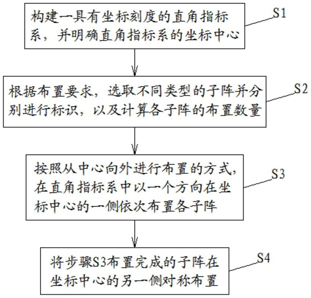
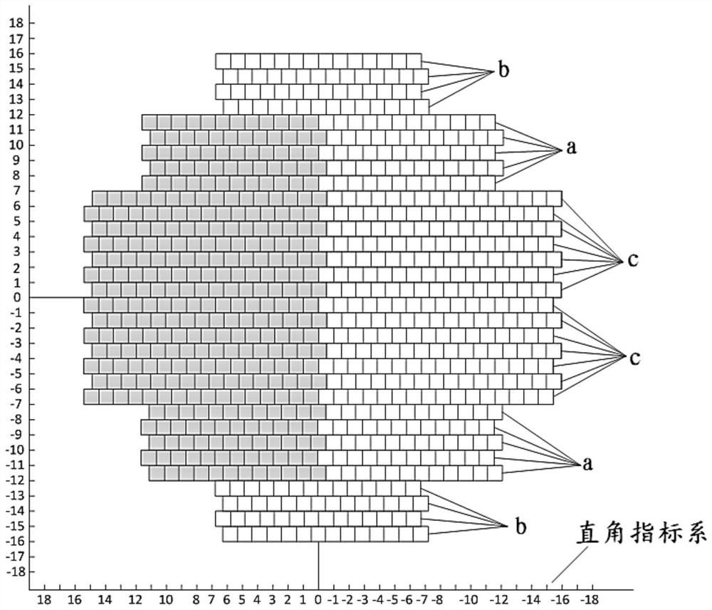
[0039] to combine figure 1 and figure 2 As shown, according to an embodiment of the present invention, a K-band phased array element cutting angle formation method of the present invention includes the following steps:

[0040] S1. Construct a rectangular index system with a coordinate scale, and specify the coordinate center of the rectangular index system;

[0041] S2. According to the layout requirements, select different types of sub-arrays and mark them separately, and calculate the layout quantity of each sub-array;

[0042] S3. According to the arrangement from the center to the outside, each sub-array is sequentially arranged on one side of the coordinate center in one direction in the rectangular index system;

[0043] S4. Arranging the sub-arrays arranged in step S3 symmetrically on the other side of the coordinate center.

[0044] Such as figure 2 As shown, according to an embodiment of the present invention, in step S1, according to the established rectangula...


PUM


Abstract

The invention relates to a K-band phased array element corner cutting and arraying method which comprises the following steps: S1, constructing a right-angle index system with coordinate scales, and defining the coordinate center of the right-angle index system; S2, according to arrangement requirements, selecting different types of sub-arrays and identifying the sub-arrays respectively, and calculating the arrangement number of the sub-arrays; S3, sequentially arranging the sub-arrays on one side of the coordinate center in one direction in the right-angle index system in a manner of arranging from the center to the outside; and S4, symmetrically arranging the sub-arrays arranged in the step S3 in the other side of the coordinate center. Through the corner cut array layout of the millimeter wave phased array antenna, the sidelobe suppression of the phased array is greatly improved.

Description

technical field [0001] The invention relates to the technical field of phased array layout, in particular to a K-band phased array element cutting angle formation method. Background technique [0002] Due to the obvious advantages of digital beamforming of phased array antennas, such as high pointing accuracy and link gain design efficiency, it is becoming a research hotspot in the field of antennas today, and has been widely used in satellite communications, measurement and control and other fields. However, considering the complex process of millimeter-wave phased array elements and transceiver components and high processing difficulty, the development cost of general phased arrays is relatively high, especially the design of millimeter-wave phased arrays requires more expensive gold wire bonding. Based on this, the following problems are faced in the design of phased array antenna array elements: 1. How to realize the optimal design of phased array antenna array under the...

Claims


Application Information

Patent Timeline
IPC IPC(8): H01Q3/34H01Q25/00
CPCH01Q3/34H01Q25/00
Inventor 王威郑晓冬高昕赵大鹏孙亮亮申建华周晖
Owner NO 63921 UNIT OF PLA
Learn More