Eureka AIR delivers breakthrough ideas for toughest innovation challenges, trusted by R&D personnel around the world.

Embedded permanent magnet variable-frequency motor rotor

A variable frequency motor, built-in technology, applied in the direction of magnetic circuit rotating parts, electromagnetic field shielding, magnetic circuit shape/style/structure, etc., can solve the problems of increased rotor wear, rotor dynamic balance failure, difficult assembly, etc., to achieve The effect of reducing magnetic field loss, reducing manufacturing difficulty, and speeding up production

Active Publication Date: 2020-11-13
ZHEJIANG XILING
View PDF6 Cites 0 Cited by
  • Summary
  • Abstract
  • Description
  • Claims
  • Application Information

AI Technical Summary

Problems solved by technology

The existing built-in permanent magnet motor rotating permanent magnet mainly fixes the permanent magnet in the permanent magnet groove by using resin, viscose and other fillers, or sets a protrusion on the edge of the permanent magnet groove, and uses the permanent magnet and the permanent magnet groove The cooperation between them, and the use of resin, viscose and other fillers to fix the permanent magnet 4 in the permanent magnet groove, but both solutions have fillers that are affected by heat and aging, resulting in failure of the filler and unable to fully fix the permanent magnet. , the permanent magnet is loose, which affects the normal operation of the motor
At the same time, it is difficult to assemble through fillers such as resin and viscose, and after the rotor is scrapped, it is difficult to disassemble and it is not easy to recycle raw materials
[0003] There are also some technical solutions in the prior art, such as the Chinese patent application number CN201721885663.1, which includes a rotor core, the rotor core is a cylindrical structure, and a circular through hole is set in the middle of both ends of the rotor core. The diameter of the left through hole is larger than that of the right through hole. A magnetic steel groove is set on one end face of the larger through hole of the rotor core. The magnetic steel groove is semicircular. Three rivet holes are evenly arranged on the end face of the rotor core, and a magnetic isolation sheet is arranged at the end of the rotor core where the magnetic steel groove is set, and the magnetic isolation sheet is riveted together with the rotor iron core by rivets; in this scheme, by setting the magnetic steel The groove and the magnetic spacer are fixed by rivets, which reduces the difficulty of rotor assembly. However, during use, it cannot be guaranteed that the magnet will not move in the magnet groove. It is easy to cause differences in the specifications of the magnet, resulting in There is a small displacement of steel in the magnetic steel groove, which leads to the failure of the dynamic balance of the rotor, aggravates the wear of the rotor, and shortens the service life of the rotor

Method used


Image

  • Embedded permanent magnet variable-frequency motor rotor
  • Embedded permanent magnet variable-frequency motor rotor
  • Embedded permanent magnet variable-frequency motor rotor

Examples


Embodiment approach

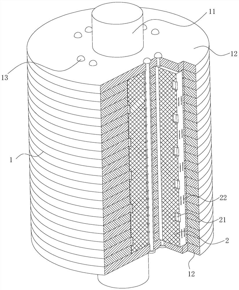
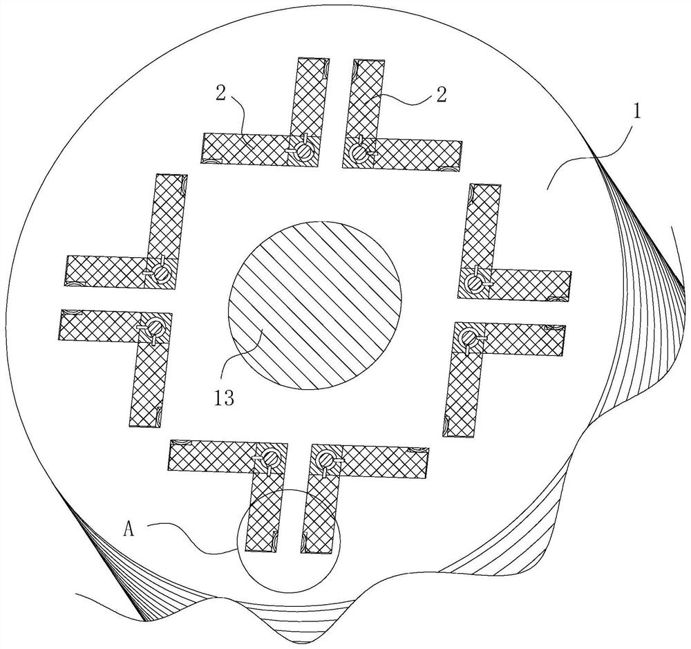
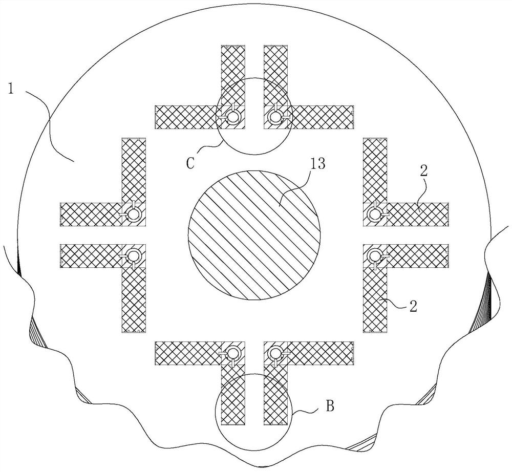
[0035] As an embodiment of the present invention, the main body 1 is obtained by stacking and fixing laminations on the rotating shaft 11; the laminations include the first lamination 23, the second lamination 24 and the third lamination 25; the main body The first lamination 23 in 1 is separated from the second lamination 24 by the third lamination 25; the lamination is obtained by stamping a thin silicon steel sheet; the first lamination 23 is provided with radial grooves 26 and tangential grooves 27; the radial groove 26 and the tangential groove 27 on the No. 1 lamination 23 are provided with a reed 28 on the side wall; the No. 2 lamination 24 is provided with a radial groove 26 and a tangential groove 27; The radial groove 26 on the No. 2 lamination 24 and the side wall of the tangential groove 27 are provided with a card 29; the card 29 on the side wall of the radial groove 26 on the No. One end of the tangential groove 27; the card 29 on the side wall of the tangential ...


PUM


Abstract

The invention belongs to the technical field of motors, and particularly relates to an embedded permanent magnet variable-frequency motor rotor which comprises a main body, and a rotating shaft is mounted in the middle of the main body; a radial groove and a tangential groove are formed in the main body; permanent magnets are mounted in the radial grooves and the tangential grooves; reeds are mounted on the side wall of the tangential grooves; reeds are mounted on the side walls of the radial grooves; an open slot is formed in the side surface of the permanent magnet; the convex part on the reed can be inserted into the open slot; an arc-shaped stop block is arranged at an inlet of the open slot; and the radial grooves and the tangential grooves in the main body jointly form a mixed permanent magnet mounting mode. According to the invention, the rotor assembly difficulty can be reduced, the permanent magnets in the rotor are fully fixed, the use of fillers is reduced or canceled, and the possibility of vibration of the permanent magnets is reduced.

Description

technical field [0001] The invention belongs to the technical field of motors, in particular to an embedded permanent magnet variable frequency motor rotor. Background technique [0002] The built-in motor is mainly composed of a stator and a rotor as a whole. The stator is fixed and consists of a stator body and windings. The stator body is made of laminated stator laminations, and the windings are wound around the teeth of the stator body. The rotor rotates and is composed of a rotor body and a permanent magnet. The rotor body is formed by stacking rotor laminations. A permanent magnet slot is arranged inside the rotor body, and the permanent magnet is fixed in the permanent magnet slot. The existing built-in permanent magnet motor rotating permanent magnet mainly fixes the permanent magnet in the permanent magnet groove by using resin, viscose and other fillers, or sets a protrusion on the edge of the permanent magnet groove, and uses the permanent magnet and the perman...

Claims


Application Information

Patent Timeline
Patent Type & Authority Applications(China)
IPC IPC(8): H02K1/27H02K1/04H02K11/01H02K1/32
CPCH02K1/04H02K1/27H02K1/32H02K11/01
Inventor 杨学良
Owner ZHEJIANG XILING
Why Eureka
Eureka Blog
Learn More