Brushless direct-current motor
A technology for brushless DC motors and components, which is used in electrical components, electromechanical devices, electric components, etc.
- Summary
- Abstract
- Description
- Claims
- Application Information
AI Technical Summary
Problems solved by technology
Method used
Image
Examples
specific Embodiment approach 1
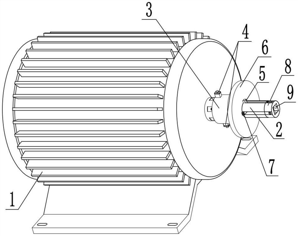
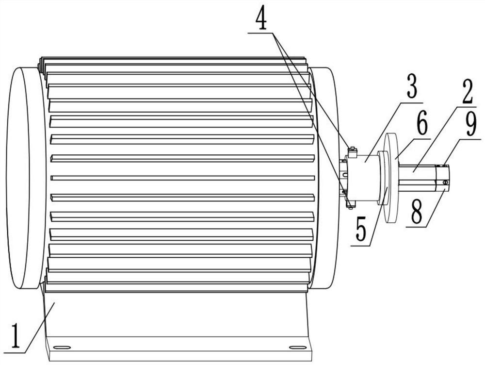
[0035] Combine below Figure 1-13This embodiment is described. The present invention relates to the technical field of motor equipment, more specifically, a brushless DC motor, which includes a motor main body component 1, an extension shaft component 2, a connecting sleeve component 3, a lifting column limiting component 4, a limiting component The position sleeve member 5, the gear main body member 6, the limit extrusion device 7, the end sleeve bearing member 8 and the extrusion fixing device 9, when the device needs to drive the gear to rotate, first fix the device, and connect the gear with the gear to be transmitted. The supporting gear 6-1 is taken out, and the gear 6-1 is installed, and according to the position of the driven gear, the position of the abutment ring 5-2 can be adjusted, and the position of the gear 6-1 can be adjusted to ensure that the gear 6-1 1 is meshed with the gear to be driven, and the expansion plate 7-2 is used to limit the position. At this ti...
specific Embodiment approach 2
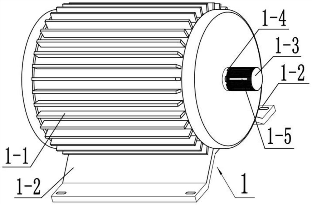
[0038] Combine below Figure 1-13 Describe this embodiment, this embodiment will further explain Embodiment 1. The motor main body component 1 includes a housing 1-1, a support 1-2, an output shaft 1-3, a processing plane 1-4 and a limiting groove 1 -5, the housing 1-1 is provided with a rotor and a stator to form a brushless DC motor. There are two supports 1-2 fixedly connected to the bottom of the motor 1-1, and the two supports 1-2 are used to connect the motor 1-2. 1 for fixing, the support 1-2 is provided with a long sliding hole, which is convenient for screws to pass through for fixing, the output shaft 1-3 is fixedly connected with the rotor in the housing 1-1, and the output shaft 1-3 is provided with threads, Six processing planes 1-4 are arranged on the output shaft 1-3, and the processing plane 1-4 can provide space for setting the limiting groove 1-5, and the six processing planes 1-4 are all provided with limiting grooves 1-5 , the limit groove 1-5 can provide ...
specific Embodiment approach 3
[0040] Combine below Figure 1-13 Describe this embodiment, this embodiment will further explain the second embodiment, the extension shaft member 2 includes a connecting shaft 2-1, a through groove 2-2, a keyway 2-3 and a threaded hole 2-4, the connecting shaft 2 -1 is fixedly connected with the output shaft 1-3, the connecting shaft 2-1 can rotate with the output shaft 1-3, the connecting shaft 2-1 is provided with a through groove 2-2, and the through groove 2-2 can be a linkage cavity 7-1 provides a sliding space, the connecting shaft 2-1 is provided with a keyway 2-3, the keyway 2-3 can provide a sliding space for the limit key 5-3, and both ends of the keyway 2-3 are provided with chamfers After being provided with chamfering, the convenient limit key 5-3 is slidably connected in the keyway 2-3, and the keyway 2-3 is provided with a plurality of threaded holes 2-4, and the plurality of threaded holes 2-4 can be fixed screws 5- 4 Provide space for connections.
PUM
 Abstract
Description
Claims
Application Information
 - R&D Engineer
- R&D Manager
- IP Professional
- Industry Leading Data Capabilities
- Powerful AI technology
- Patent DNA Extraction
Browse by: Latest US Patents, China's latest patents, Technical Efficacy Thesaurus, Application Domain, Technology Topic, Popular Technical Reports.
© 2024 PatSnap. All rights reserved.Legal|Privacy policy|Modern Slavery Act Transparency Statement|Sitemap|About US| Contact US: help@patsnap.com


