Oral implantation auxiliary positioning device and positioning method thereof

A technology that assists positioning and oral cavity. It is applied in the fields of implantology, medical science, dentistry, etc. It can solve problems such as implant tooth deviation and achieve the effect of easy disassembly.

Active Publication Date: 2020-11-17
漯河市第一人民医院
View PDF10 Cites 0 Cited by
  • Summary
  • Abstract
  • Description
  • Claims
  • Application Information

AI Technical Summary

Problems solved by technology

[0003] In oral implantology, drilling the alveolar bone to place the implant is a critical step. Most of the existing drilling methods rely on the doctor’s experience. If there is a deviation in the drilling, the implant will easily appear incompatible with other teeth. Offset phenomenon

Method used


Image

  • Oral implantation auxiliary positioning device and positioning method thereof
  • Oral implantation auxiliary positioning device and positioning method thereof
  • Oral implantation auxiliary positioning device and positioning method thereof

Examples


Embodiment 1

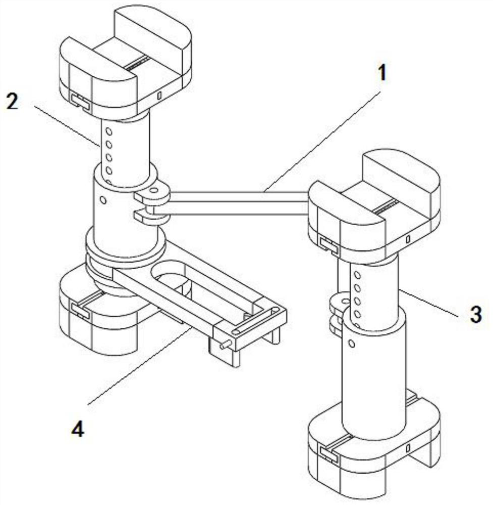
[0043] Such as figure 1 The oral implant auxiliary positioning device shown includes a V-shaped connecting frame 1 and a relatively symmetrical first support frame 2 and a second support frame 3 that are rotatably installed at both ends of the V-shaped connecting frame 1. The outside of the first support frame 2 A positioning mechanism 4 is installed in rotation.

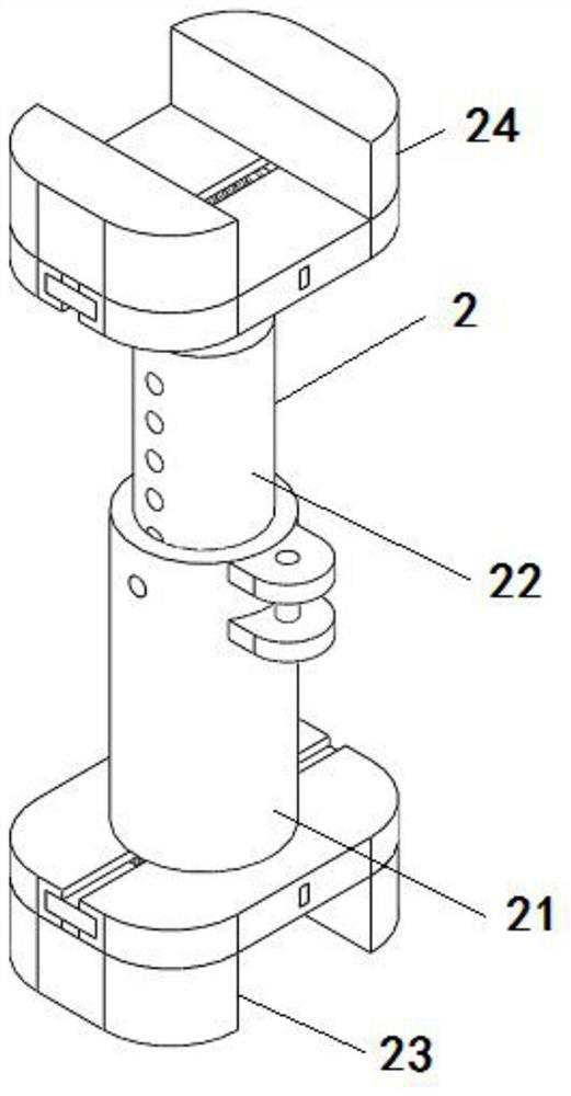
[0044] Such as Figure 2 to Figure 5 As shown, the first support frame 2 includes a support sleeve 21 and a connecting slide bar 22 that are slidably connected. Fastening mechanism 24, the first fastening mechanism 23 and the second fastening mechanism 24 are structurally symmetrical;

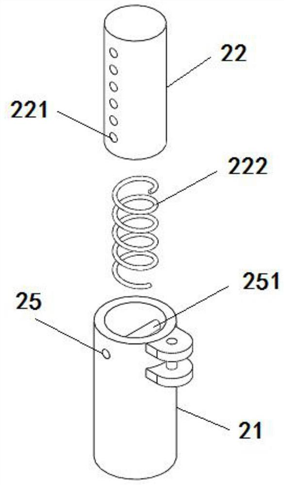
[0045] The side of the support sleeve 21 is provided with a first threaded hole 25, the first threaded hole 25 is internally threaded with a first bolt 251, and the side of the connecting slide bar 22 is evenly distributed with a second threaded hole 221 matched with the first bolt 251;

[0046]A second spring 222 is fixedly insta...

Embodiment 2

[0063] A positioning method of an auxiliary positioning device for oral implant, the method comprising the following steps:

[0064] Step a: When implanting the middle part of the patient's oral cavity, place the first support frame 2 and the second support frame 3 in the patient's oral cavity, rotate the connecting collar 41, and place the first compression plate 4541 and the second compression plate 4551 Placed on both sides of the site to be planted;

[0065] Step b: Tighten the threaded push rod 458, tightly install the first compression plate 4541 and the second compression plate 4551 on both sides of the site to be implanted, and position the cavity 457 for guidance during oral implantation;

[0066] Step c: When implanting the two sides of the patient's mouth, disassemble the V-shaped connecting frame 1 from the first support frame 2 and the second support frame 3 respectively, and place the first support frame 2 in the middle of the patient's oral cavity after the disa...


PUM


Abstract

The invention discloses an oral implantation auxiliary positioning device. The device comprises a V-shaped connecting frame, a first supporting frame and a second supporting frame, wherein the first supporting frame and the second supporting frame are symmetrically and rotationally installed at two ends of the V-shaped connecting frame; and a positioning mechanism is rotationally installed outsidethe first supporting frame. Through the arrangement of the first supporting frame and the second supporting frame, the positioning mechanism can be stably placed in the oral cavity of a patient, andthe size is adjusted according to the conditions of different patients; through the arrangement of the positioning mechanism, a positioning cavity is used for conducting auxiliary positioning on alveolar bone drilling, so that the phenomenon that a subsequent implant deviates due to drilling deviation is prevented; and through the arrangement of the V-shaped connecting frame, disassembly is convenient, and the auxiliary positioning device is suitable for auxiliary positioning of different implantation parts in the oral cavity of the patient. The invention further provides a positioning methodof the oral implantation auxiliary positioning device. Through the arrangement of the method, a basis is provided for the oral implantation auxiliary positioning device.

Description

technical field [0001] The invention belongs to the technical field of biomedical devices, and in particular relates to an auxiliary positioning device for oral implantation and a positioning method thereof. Background technique [0002] Dental implants are generally a restoration method in which pure titanium screws (commonly called implants) are implanted into the alveolar bone, and then dentures are made on the implants. The implant in the alveolar bone is equivalent to our natural tooth root. Since it can grow closely with the alveolar bone, it can stably support the dentures exposed outside the gums. [0003] In oral implantology, drilling the alveolar bone to place the implant is a critical step. Most of the existing drilling methods rely on the doctor’s experience. If there is a deviation in the drilling, the implant will easily appear incompatible with other teeth. shifting phenomenon. Contents of the invention [0004] The purpose of the present invention is to ...

Claims


Application Information

Patent Timeline
IPC IPC(8): A61C3/02A61C8/00
CPCA61C3/02A61C8/0089
Inventor 胡豪杰
Owner 漯河市第一人民医院
Why Eureka
Try Eureka