Magic cube, incremental molded surface rotation sensor and axis structure thereof

A rotational sensor, incremental technology, applied in the field of Rubik's Cube, which can solve the problems of single function of Rubik's Cube, inability to communicate with external electronic devices, and complex internal structure of Rubik's Cube.

Pending Publication Date: 2020-11-17
汕头市澄海区魔域文化有限公司
View PDF1 Cites 0 Cited by
  • Summary
  • Abstract
  • Description
  • Claims
  • Application Information

AI Technical Summary

Problems solved by technology

[0003] At present, the commonly used Rubik's Cube has a single function, cannot communicate with external electronic devices, and lacks interest
In order to improve the fun of Rubik's Cube operation, some electronic Rubik's Cubes have appeared in the prior art, that is, electronic components such as sensors are arranged on the Rubik's Cube to detect the surface rotation information of the Rubik's Cube, etc., but in the prior art due to problems such as sensor volume and area It cannot be put into the inner ball in the center of the Rubik's Cube, which makes the internal structure of the Rubik's Cube more complicated
For example, the Chinese invention patent application with the publication number CN106110651A discloses a smart Rubik's Cube and its use of the induction axis structure timing method, wherein the state signal sending group for generating the state signal, that is, the sensor is arranged on the tubular shaft outside the Rubik's cube inside the inner sphere The central block, the data and electrical connection between the sensor and the inner ball are connected by a hollow tubular shaft. During the rotation of the Rubik’s Cube, the tubular shaft and the state signal sending group on it will also rotate together, which will inevitably cause the tubular shaft to rotate. The twisting of the inner circuit, after a certain period of use of the Rubik's Cube, will lead to the twisting of the inner circuit of the tubular shaft, which reduces the service life of the Rubik's Cube; Corresponding Rubik's Cube modules (including center blocks, corner blocks and edge blocks) are required, and cannot be compatible with traditional Rubik's Cube modules
[0004] In addition, in the prior art, the sensor used for angle detection in the prior art can use an incremental encoder, but the existing incremental encoder is not suitable for the Rubik's Cube at all, mainly because the installation dimensions such as volume thickness cannot reach the Rubik's Cube Requirements, the Rubik's Cube is a polyhedron, the incremental encoder is used for surface rotation detection, the use of multiple separate incremental encoders is not conducive to installation and maintenance, and the encoder used for the Rubik's Cube must adopt a single-ring design and must maintain a certain detection accuracy to ensure Detection data can be used for AI analysis of Rubik's Cube data

Method used


Image

  • Magic cube, incremental molded surface rotation sensor and axis structure thereof
  • Magic cube, incremental molded surface rotation sensor and axis structure thereof
  • Magic cube, incremental molded surface rotation sensor and axis structure thereof

Examples


Embodiment 1

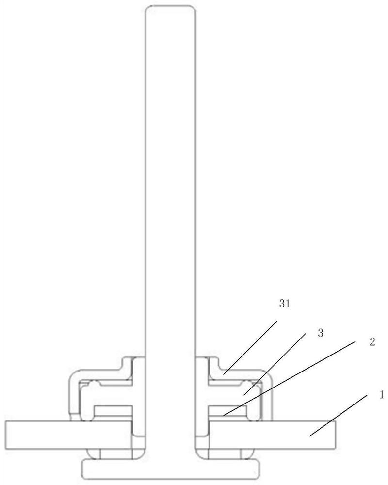
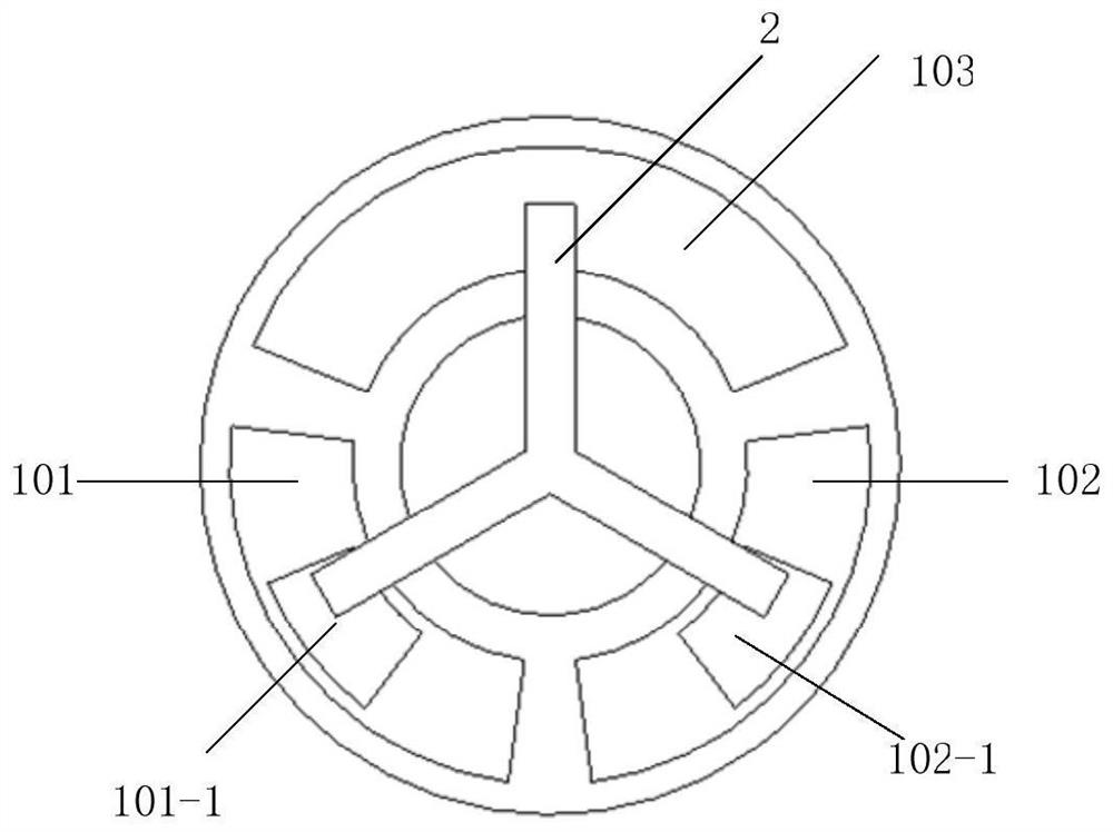
[0068] This embodiment discloses a Rubik's Cube incremental surface rotation sensor, such as figure 1 As shown, it includes a code wheel 1, a first brush 2 and a first rotor 3, the code wheel is provided with a first electrode, a second electrode and a third electrode, and the first electrode, the second electrode and the third electrode are arranged on the code wheel On the same circle of the disk surface, define the circle as the first circle; the first brush includes three endpoints, respectively the first endpoint, the second endpoint and the third endpoint, the first endpoint of the first brush, the second The end points and the third end points are arranged along the first circle and every two end points are spaced apart Arc; the first brush is installed on the first rotor and drives the three ends of the first brush to rotate along the first circumference relative to the first electrode, the second electrode and the third electrode through the first rotor, and the firs...

Embodiment 2

[0090] This embodiment discloses a surface rotation sensor of Rubik's Cube, which differs from the surface rotation sensor of Rubik's Cube in Embodiment 1 only in that Figure 5 As shown, the surface rotation sensor of Rubik's Cube in this embodiment also includes a second rotor 4 and a second brush 5, the code disc is provided with a fourth electrode, a fifth electrode and a sixth electrode, and the fourth electrode, the fifth electrode and the sixth electrode The six electrodes are arranged on the same circumference of the code disk surface, and this circumference is defined as a second circumference; the second circumference is located on the outer circumference of the first circumference.

[0091] In this embodiment, the second brush includes three terminals, namely a first terminal, a second terminal and a third terminal, and the first terminal, the second terminal and the third terminal of the second brush are all along the The second circle is arranged and every two end...

Embodiment 3

[0107] This embodiment discloses a surface rotation sensor of Rubik's Cube, such as Figure 9 As shown, the only difference with the surface rotation sensor of Rubik's Cube in Embodiment 1 is that the surface rotation sensor of Rubik's Cube in this embodiment also includes a second rotor 4, a second brush 5, a third rotor 6 and a third brush 7, The code wheel is provided with a fourth electrode, a fifth electrode, a sixth electrode, a seventh electrode, an eighth electrode and a ninth electrode, and the fourth electrode, the fifth electrode and the sixth electrode are arranged on the same circumference of the code wheel surface, defined This circle is the second circle; the seventh electrode, the eighth electrode and the ninth electrode are arranged on the same circle of the code disc surface, and this circle is defined as the third circle; the second circle is in the outer circle of the first circle, and the third circle is in the first circle. The outer circumference of two ...


PUM


Abstract

The invention discloses a magic cube, an incremental molded surface rotation sensor and an axis structure thereof. The incremental molded surface rotation sensor comprises a coded disc, a first electric brush and a first rotor, a first electrode, a second electrode and a third electrode are arranged on the coded disc, and all the electrodes are arranged on the first circumference of the coded discsurface; the first electric brush comprises three end points, the three end points are arranged along the first circumference, and every two end points are spaced by a radian. The first electric brush is mounted on the first rotor, drives three end points on the first rotor to rotate along a first circumference relative to the upper electrode of the first rotor through the first rotor, and is incontact with the first electrode, the second electrode and the third electrode through the three end points; the radian of the third electrode on the first circumference is shown in the specification;in the magic cube, the radians of the gap between every two electrodes, the first electrode and the second electrode on the circumference are set according to the number of pulses to be realized by the sensor; according to the magic tube, the surface rotation detection precision of the magic cube is greatly improved, and the magic cube is simpler in structure and lower in cost.

Description

technical field [0001] The present invention relates to the technical field of Rubik's Cube, in particular to Rubik's Cube and its incremental surface rotation sensor and axis structure. The Rubik's Cube in the present invention covers Rubik's Cube intellectual toys, and specifically refers to all Rubik's Cubes entering the WCA (International Rubik's Cube Association) competition. Intellectual toys include Rubik's Cube of 2~7th order, Pyramid Rubik's Cube, 12-hedron 5-magic ball, oblique Rubik's Cube and SQ Rubik's Cube. Background technique [0002] Rubik's Cube, also known as Rubik's Cube, is called Rubik's Cube in Taiwan, China, and is called Rubik's Cube in Hong Kong, China. The English name is: Rubik's Cube. Toys are loved by everyone. Rubik's cube restoration refers to the process of Rubik's cube from non-original state to original state. It is a process integrating observation, hands-on and imagination. It can cultivate people's hands-on, brain-moving ability, trai...

Claims


Application Information

Patent Timeline
Patent Type & Authority Applications(China)
IPC IPC(8): A63F9/08
CPCA63F9/0842
Inventor 陈永煌刘寄张乐
Owner 汕头市澄海区魔域文化有限公司
Why Eureka
Try Eureka