
A filter tightening limit structure and tightening process

A limit structure, filter technology, applied in the direction of machine/engine, charging system, liquid fuel feeder, etc., can solve the single torque control mode or angle control mode, reduce the yield of tightening operation, soft seal It is difficult for the ring to play a sealing role, etc.

Active Publication Date: 2020-06-09
苏州斯雷克机电科技有限公司
View PDF6 Cites 0 Cited by
  • Summary
  • Abstract
  • Description
  • Claims
  • Application Information

AI Technical Summary

Problems solved by technology

[0003] In the filter assembly process in the prior art, the accuracy of the tightening operation between the upper cover and the lower housing directly determines the airtightness of the filter cavity. In order to improve the sealing accuracy, the threaded section at the lower end of the upper cover The upper smooth section is provided with a sealing ring, and the soft sealing ring is twisted and deformed during the tightening process, and it is difficult to play a sealing role; secondly, in the traditional tightening process, a single torque control method or angle control method is often adopted, which cannot be adjusted according to the actual situation of the sealing ring. Take corresponding measures in time under the stress situation, greatly reducing the yield of tightening operations

Method used

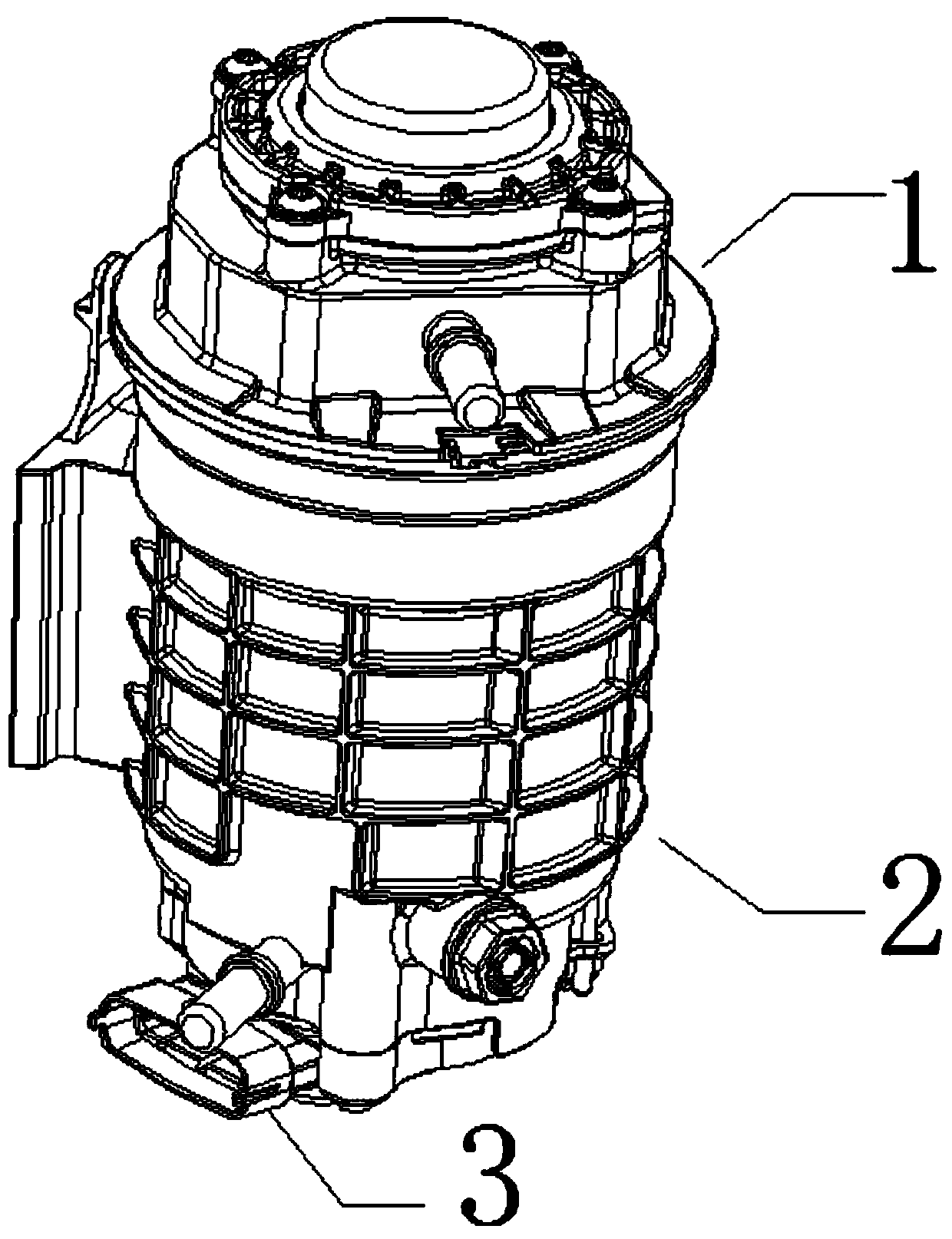

Image

  • A filter tightening limit structure and tightening process
  • A filter tightening limit structure and tightening process
  • A filter tightening limit structure and tightening process

Examples


specific Embodiment example 1

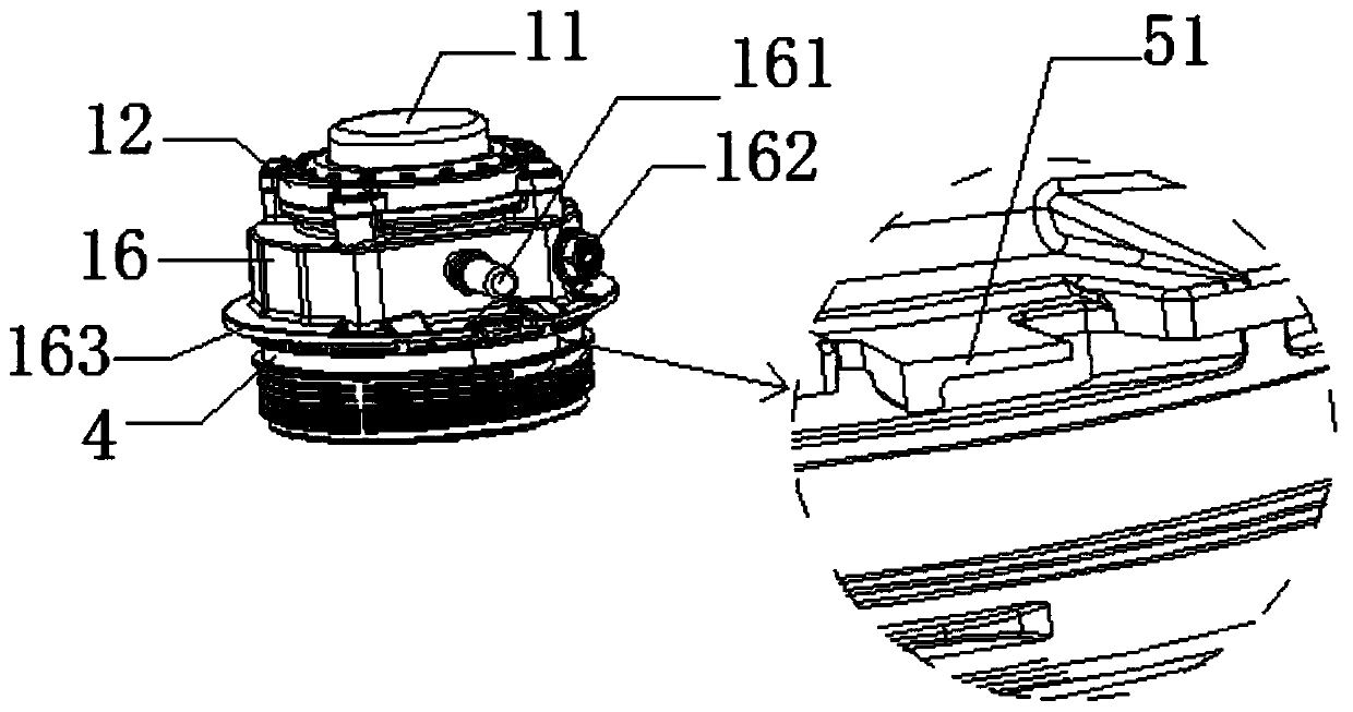
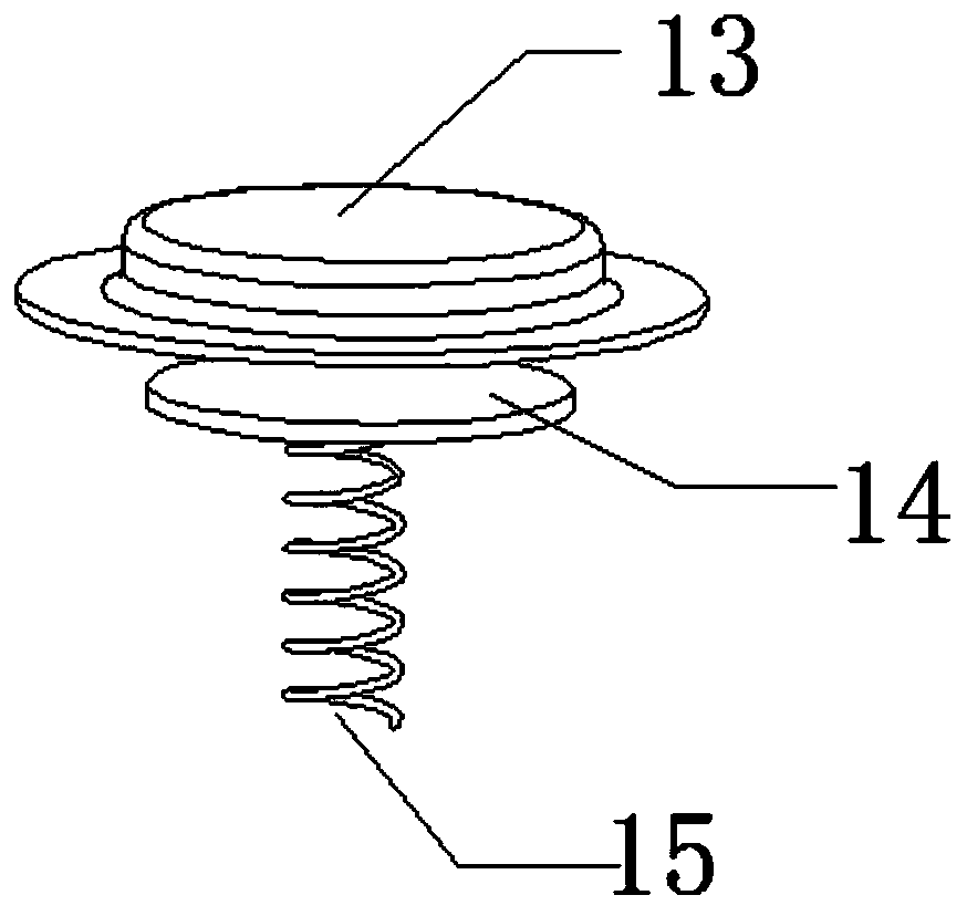
[0037] A tightening limit structure for a filter, comprising: an upper cover 1, a lower casing 2, and a combined sensor 3 installed on the base of the lower casing 2; the upper cover 1 sequentially includes a pressing handle 11, a hand The pump cover 12, diaphragm 13, support plate 14, spring 15, upper cover body 16, the support plate 14 with the spring 15 fixed on the lower end surface is placed in the upper convex cavity of the diaphragm 13, and the diaphragm 13 is installed on the upper cover The lower end of the push handle 11 is inlaid and fixed in the center hole of the hand pump cover 12 in the ring slot at the upper end of the body 16, and the upper end of the press handle 11 extends out of the center hole of the hand pump cover 12 for a length, and the spring 15 is compressed After a certain distance, the hand pump cover 12 and the upper cover body 16 are tightly attached and screwed along the circumferential direction. The circumferential side of the upper cover body ...

specific Embodiment example 2

[0051] A tightening limit structure for a filter, comprising: an upper cover 1, a lower casing 2, and a combined sensor 3 installed on the base of the lower casing 2; the upper cover 1 sequentially includes a pressing handle 11, a hand The pump cover 12, diaphragm 13, support plate 14, spring 15, upper cover body 16, the support plate 14 with the spring 15 fixed on the lower end surface is placed in the upper convex cavity of the diaphragm 13, and the diaphragm 13 is installed on the upper cover The lower end of the push handle 11 is inlaid and fixed in the center hole of the hand pump cover 12 in the ring slot at the upper end of the body 16, and the upper end of the press handle 11 extends out of the center hole of the hand pump cover 12 for a length, and the spring 15 is compressed After a certain distance, the hand pump cover 12 and the upper cover body 16 are tightly attached and screwed along the circumferential direction. The circumferential side of the upper cover body ...

specific Embodiment example 3

[0065] A tightening limit structure for a filter, comprising: an upper cover 1, a lower casing 2, and a combined sensor 3 installed on the base of the lower casing 2; the upper cover 1 sequentially includes a pressing handle 11, a hand The pump cover 12, diaphragm 13, support plate 14, spring 15, upper cover body 16, the support plate 14 with the spring 15 fixed on the lower end surface is placed in the upper convex cavity of the diaphragm 13, and the diaphragm 13 is installed on the upper cover The lower end of the push handle 11 is inlaid and fixed in the center hole of the hand pump cover 12 in the ring slot at the upper end of the body 16, and the upper end of the press handle 11 extends out of the center hole of the hand pump cover 12 for a length, and the spring 15 is compressed After a certain distance, the hand pump cover 12 and the upper cover body 16 are tightly attached and screwed along the circumferential direction. The circumferential side of the upper cover body ...


PUM


Abstract

The invention discloses a tightening limiting structure of a filter. An upper cover body and a lower shell are provided with a buckle positioning module with a rotating angle of 0.8-1.5 degrees; the buckle positioning module comprises an L-shaped buckle plate on the cover plate edge of the upper cover body, and a buckle groove on the upper end surface of the upper shell; and through a buckling effect between the L-shaped buckle plate and the buckle groove, reduction of the internal tightness of a filter cavity due to reversal in the reverse torque suffering process is prevented when the anglepositioning precision in a tightening process is improved. The tightening process with the filter with the tightening limiting structure comprises the steps of tool clamping fixation, initial positiondetection, tightening and tightening limiting; and in the tightening and tightening limiting steps, part reversal operation is related, and can be controlled by a control system according to data transmitted by a torque sensor or according to a friction torque value and an angle rotation lap number, so that the integrity of a sealing ring in the tightening procedure is further guaranteed, and thetightness of the filter and the yield in the tightening procedure are improved.

Description

technical field [0001] The present invention relates to the field of filter mechanical equipment technology and assembly technology for oil filtration and separation, and specifically relates to a tightening limit structure and a tightening process of a filter. Background technique [0002] The function of the gasoline filter is to filter out the moisture and impurities in the gasoline. When the engine is working, the fuel, under the action of the gasoline pump, enters the sedimentation cup of the filter through the oil inlet pipe. As the volume becomes larger and the flow rate becomes smaller at this time, water and impurity particles heavier than oil settle at the bottom of the cup, light impurities flow to the filter element with the fuel, and clean fuel seeps into the filter element from the micropores of the filter element, and then It flows out through the fuel pipe to avoid impurities in the oil from clogging the pipeline and avoiding damage to the engine's fuel inje...

Claims


Application Information

Patent Timeline
Patent Type & Authority Patents(China)
IPC IPC(8): F02M37/42
CPCF02M37/22
Inventor 蒋庆松
Owner 苏州斯雷克机电科技有限公司
Learn More