A high-speed motor rotor position detection device and processing method

A technology of rotor position and processing method, which is applied in the direction of electronic commutator, etc., can solve the problems of incorrect rotor position angle, long transmission distance of resolver feedback signal, easy interference of feedback signal, etc., and achieve the effect of improving anti-interference performance

Inactive Publication Date: 2017-01-18
CHINA XD ELECTRIC CO LTD +1
View PDF4 Cites 0 Cited by
  • Summary
  • Abstract
  • Description
  • Claims
  • Application Information

AI Technical Summary

Problems solved by technology

[0004] The existing technology has the following disadvantages: the transmission distance between the decoding unit and the controller is short, and some industrial field frequency converters are far away from the motor, which requires a relatively long distance between the decoding unit and the resolver, so that the resolver feedback signal The transmission distance is relatively long. In the long-distance transmission, the resolver feedback signal is easily disturbed, resulting in incorrect rotor position and angle obtained by the controller, which deviates from the actual rotor angle position.

Method used


Image

  • A high-speed motor rotor position detection device and processing method
  • A high-speed motor rotor position detection device and processing method
  • A high-speed motor rotor position detection device and processing method

Examples


Embodiment Construction

[0049] The present invention is described in detail below in conjunction with accompanying drawing and specific embodiment:

[0050] In order to clearly illustrate the solutions in the present invention, preferred embodiments are given below and detailed descriptions are given in conjunction with the accompanying drawings.

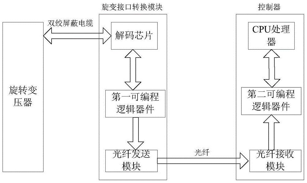
[0051] image 3 It is a block diagram of the realization of the scheme of this embodiment. The detection device includes: a rotary transformer, which is used to connect with the synchronous motor, and feeds back the rotor position signal after receiving the excitation signal;

[0052] sender, including:

[0053] The decoding chip provides the excitation signal for the resolver, and calculates the digital signal corresponding to the rotor according to the signal fed back by the resolver; at the same time, it judges whether the signal feedback is normal, and outputs the above signal through a parallel bus or a serial bus;

[0054] The first programmable lo...


PUM


Abstract

The invention discloses a detection device and processing method of a high-speed motor rotor position. The method comprises the following steps: reading a most recently received rotor position signal; analyzing an angular value Theta fd from the rotor position signal; determining the compensated angle Theta cmd according to the following formula: Theta cmd= Theta fd+Omega Gamma*N*Tcnt, wherein Omega Gamma is an angular velocity determined according to the angular value obtained by analyzing previous two rotor position signals; Omega Gamma=(Theta cmd1-Theta cmd2) / t, wherein t is time interval between Theta cmd1 and Theta cmd2; N*Tcnt is time interval between the reading and the most recently receiving; N is a time delay count value, and Tcnt is the period of a time delay count pulse. According to the device and method disclosed by the invention, the interference resistance of the signal in the transmission process is improved, the signal transmission distance is increased, and the detection precision of the rotor angle is improved.

Description

technical field [0001] The invention belongs to the technical field of motors, and in particular relates to a detection device and a processing method for the rotor position of a high-speed motor. Background technique [0002] Permanent magnet synchronous motors are widely used due to their high power density, low inertia, and high efficiency, especially in high-speed applications. In order to achieve maximum torque output, permanent magnet synchronous motors must know accurate rotor absolute position signals. Generally, position feedback Devices include absolute photoelectric encoders, Hall sensors, resolvers, etc., and resolvers are widely used in servo systems due to their reliable structure, good real-time performance, and strong environmental adaptability. [0003] The traditional method of using a resolver to detect the rotor position is that the signal fed back by the resolver passes through the decoding unit and then sends the position signal to the controller in the...

Claims


Application Information

Patent Timeline
Patent Type & Authority Patents(China)
IPC IPC(8): H02P6/16
Inventor 廖文建李明才苏位峰卫三民苟锐锋
Owner CHINA XD ELECTRIC CO LTD
Why Eureka
Try Eureka