Dust falling device for constructional engineering

A dust suppression device and construction engineering technology, applied to the separation of dispersed particles, chemical instruments and methods, and the use of liquid separation agents, etc., can solve the problem that water pipes cannot be moved at will, and achieve the effect of improving service life and dust reduction

Active Publication Date: 2020-11-17
中安(潮州)建设有限公司
View PDF14 Cites 1 Cited by
  • Summary
  • Abstract
  • Description
  • Claims
  • Application Information

AI Technical Summary

Problems solved by technology

[0005] In order to overcome the current method of dust reduction on construction sites, which can only spray water in a single direction, and the water pipe needs to be connected to the equipment and cannot be moved at will, the technical problem of the present invention is to provide a method that can spray water in different directions, Dust suppression device for construction works where the equipment can be moved freely to a suitable location

Method used


Image

  • Dust falling device for constructional engineering
  • Dust falling device for constructional engineering
  • Dust falling device for constructional engineering

Examples


Embodiment 1

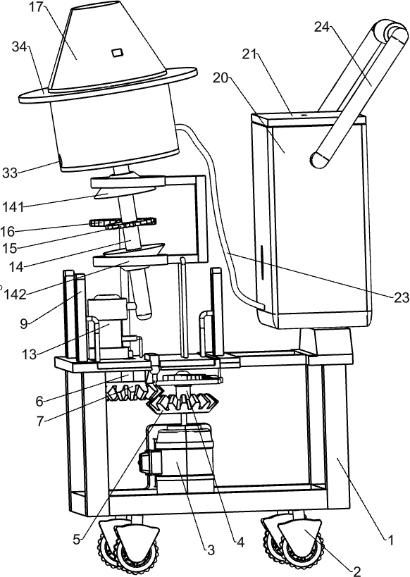
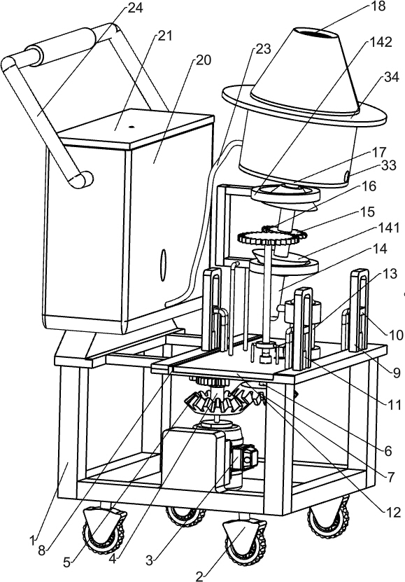
[0022] A dust suppression device for construction engineering, such as Figure 1-4 As shown, it includes a mounting frame 1, wheels 2, driving components, lifting components, rotating components, water spray components and pushing components. The mounting frame 1 is used to install the entire device. The bottom of the mounting frame 1 is provided with wheels 2. There is a driving component at the top, which is powered by a motor. There is a lifting component on the top of the installation frame 1, which can be lifted and lowered by sliding. The component is converted into water mist by inhaling a water source. The upper part of the installation frame 1 is provided with a pushing component, which is pushed by sliding, and the pushing component cooperates with the lifting component.

[0023] Such as figure 1 , 2 As shown in and 4, the drive assembly includes a reduction motor 3, the first rotating rod 4, the first bevel gear 5, the telescopic rod 6 and the second bevel gear 7,...

Embodiment 2

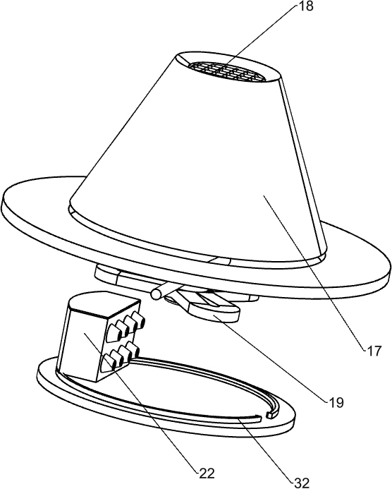
[0035] On the basis of above-mentioned embodiment 1, as Figure 1-3 As shown, it also includes an annular guide block 32, the inner bottom of the conical cylinder 17 is provided with an annular guide block 32, and there is a gap on the annular guide block 32, and a through hole 33 is provided at the bottom of the conical cylinder 17. The notch cooperates with the through hole 33 .

[0036] On the basis of Embodiment 1 above, a circular baffle 34 is also included, and the upper part of the conical cylinder 17 is provided with a circular baffle 34 .

[0037] The concrete operation process of above-mentioned embodiment: as Figure 1-3 As shown, when the conical cylinder 17 rotates, the ring guide block 32 is driven to rotate, and at the same time, the through hole 33 on the conical cylinder 17 is driven to rotate. The gap on the block 32 cooperates with the through hole 33, so that the water remaining in the conical cylinder 17 can be quickly cleaned and poured out.

[0038] W...


PUM


Abstract

The invention relates to a dust falling device, in particular to a dust falling device for constructional engineering. According to the dust falling device for constructional engineering, water can besprayed in different directions, and equipment can be moved to a proper position at will. A dust settling device for constructional engineering comprises a mounting frame, used for mounting the wholedevice; wheels, which are mounted on the mounting frame; a driving assembly, which is mounted on the mounting frame and is powered by a motor; a lifting assembly, which is mounted on the mounting frame and vertically moves in a sliding mode; a rotating assembly, which is mounted on the lifting assembly and is powered by the driving assembly to rotate; a water spraying assembly, which is mounted on the mounting frame and is converted into water mist by sucking in a water source; and a pushing assembly, which is installed on the installation frame and pushed in a sliding mode and is matched with the lifting assembly. Through cooperation of the small gear and the large gear, water can be sprayed in different directions in the air.

Description

technical field [0001] The invention relates to a dust-reducing device, in particular to a dust-reducing device for construction engineering. Background technique [0002] The Architectural Engineering major is mainly responsible for the teaching and management of the Architectural Engineering direction of the Civil Engineering major. It mainly cultivates and masters the basic theories and basic knowledge of engineering mechanics, soil mechanics, surveying, building architecture and structural engineering disciplines. During construction on the construction site, when large dust floats into the air, workers need to sprinkle water to reduce dust. [0003] Patent Publication No. CN210561630U discloses a sprinkler device for road construction, including a water tank chassis, the upper surface of the water tank chassis is fixedly connected with a water tank, and the lower surface of the water tank chassis is fixedly connected with a hydraulic rod. The lower surface of the hydra...

Claims


Application Information

Patent Timeline
Patent Type & Authority Applications(China)
IPC IPC(8): B01D47/08
CPCB01D47/08
Inventor 肖春莲
Owner 中安(潮州)建设有限公司
Why Eureka
Try Eureka