Tool box for constructional engineering field work measurement

A construction engineering and toolbox technology, which is applied in the field of measuring toolbox devices, can solve problems such as tool damage, increased load, and increased burden on students to carry, so as to achieve the effect of easy search and avoid random shaking

Active Publication Date: 2020-11-17
HEBEI INSTITUTE OF ARCHITECTURE AND CIVIL ENGINEERING
View PDF8 Cites 3 Cited by
  • Summary
  • Abstract
  • Description
  • Claims
  • Application Information

AI Technical Summary

Problems solved by technology

The measuring rod consists of a circular ring and a vertical rod. The rod is connected to the lower end of the ring. Generally, several of them need to be carried at the same time. Due to the special shape of the measuring rod, it is inconvenient to carry
There are many types of tools that need to be carried, and the sizes are different, so it is inconvenient to carry
If all the t

Method used


Image

  • Tool box for constructional engineering field work measurement
  • Tool box for constructional engineering field work measurement
  • Tool box for constructional engineering field work measurement

Examples


Embodiment 1

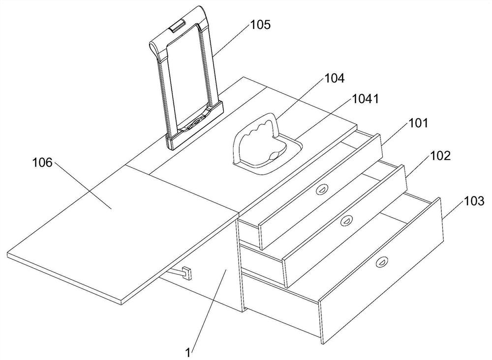
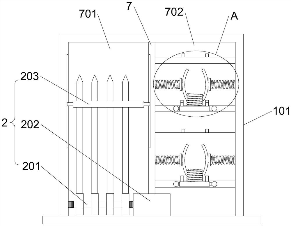
[0039] The toolbox for construction engineering field measurement of the present invention comprises a box body 1, a first drawer 101, a second drawer 102 and a third drawer 103 arranged sequentially from top to bottom are arranged in the box body 1, and the outer wall of the box body 1 is arranged There is a pull rod 105, the side wall of the box body 1 is provided with a folding plate 106, the upper end of the box body 1 is hinged with a handle 104, and the first partition plate 7 is arranged in the first drawer 101 to divide the first drawer 101 into a drilling cavity 701 And the tape measure cavity 702, the drill measuring cavity 701 is provided with a measuring drill fixing part 2, and the tape measure cavity 702 is provided with a tape measure fixing part 3; the middle part of the second drawer 102 is provided with a positioning block 401, and the upper end of the positioning block 401 is provided with a guide plate 4 for positioning A plurality of elastic pressing assemb...

Embodiment 2

[0042] This embodiment is further optimized on the basis of Embodiment 1 as follows: the brazing fixing part 2 includes a sleeve rod 201, a positioning plate 202 and a brazing plate 203; the positioning plate 202 runs through the first partition 7, and the positioning plate 202 is horizontal There is a threaded hole through it, and the outer wall of one end of the sleeve rod 201 is provided with an external thread that is compatible with the threaded hole. A plurality of through holes are opened, and the drilling plate 203 can move along the direction vertical to the sleeve rod 201 . Both ends of the drill measuring plate 203 are provided with limiting projections, and the inner wall of the drill measuring chamber 701 is provided with limiting grooves that are compatible with the limiting projections.

[0043] After adopting the above-mentioned technical scheme: the measuring drill fixing part 2 penetrates through the annular part of the measuring drill through the sleeve rod ...

Embodiment 3

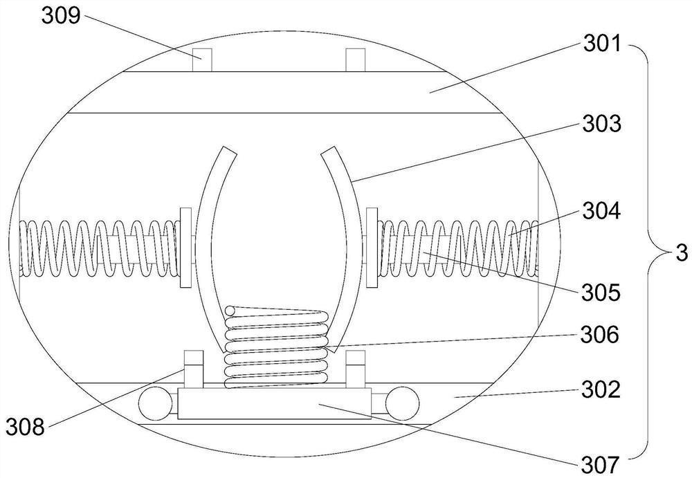
[0045] The present embodiment is further optimized on the basis of Embodiment 1 as follows: the tape measure fixture 3 includes a first support plate 301, a second support plate 302, a pressing plate 303, a pressing spring 304, a cover plate 307, Compression spring 306; the first support plate 301 and the second support plate 302 are arranged in the tape cavity 702 parallel to each other, and the pressing plate 303 is symmetrically arranged between the first support plate 301 and the second support plate 302 , the outer side of the pressing plate 303 is provided with a guide post 305, the pressing spring 304 is sleeved on the guiding post 305, the pressing spring 304 is located between the pressing plate 303 and the inner wall of the tape measure chamber 702, and the cover plate 307 is hingedly mounted on the first On the upper end of the support plate 301, the cover plate 307 is provided with a buckle sub-part 308, the second support plate 302 is provided with a buckle female ...


PUM


Abstract

The invention discloses a tool box for constructional engineering field work measurement, and relates to the technical field of tool box devices for measurement. The tool box comprises a box body, wherein a pull rod is arranged on the outer wall of the box body, a folding plate is arranged on the side wall of the box body, a handle is hinged to the upper end of the box body, a first partition plate is arranged in a first drawer to divide the first drawer into a survey pin cavity and a measuring tape cavity, a survey pin fixing piece is arranged in the survey pin cavity, and a measuring tape fixing piece is arranged in the measuring tape cavity; a positioning block is arranged in the middle of a second drawer, a guide plate is arranged at the upper end of the positioning block, and a plurality of elastic pressing assemblies are arranged on the periphery of the positioning block and located below the guide plate; and a third drawer is provided with a second partition plate which dividesthe third drawer into a drawing cavity and a pencil cavity, a paperweight piece is arranged in the drawing cavity, and a detachable storage bag is arranged in the pencil cavity. A user can conveniently carry various different measuring tools, the tools do not collide with one another, and the tools are prevented from being damaged.

Description

technical field [0001] The invention relates to the technical field of toolbox devices for measurement, in particular to a toolbox for field measurement in construction engineering. Background technique [0002] Students majoring in construction engineering often need to go to the construction site for field practice. During the internship and field production, students often need to carry a variety of measuring tools, such as: measuring brazing, tape measure, steel ruler, ruler, drawings, calculators, pencils, knives and chalk, etc. The measuring drill includes a circular ring and a vertical rod, and the rod is connected to the lower end of the ring. Generally, several of them need to be carried at the same time. Due to the special shape of the measuring drill, it is inconvenient to carry. There are many types of tools that need to be carried, and they are of different sizes, which is inconvenient to carry. If all the tools are directly placed in the same box space, rigid...

Claims


Application Information

Patent Timeline
IPC IPC(8): B25H3/02
CPCB25H3/021
Inventor 温婉丽李冰任志钰王玉君武艳强贾贵宝魏文博郝利成李春林刘海静杜雯静刘晨涛丁勇姜广州赵大威柴筱立王建明底素卫郭卫彤郁雯邱立军任淑萍陈景玉
Owner HEBEI INSTITUTE OF ARCHITECTURE AND CIVIL ENGINEERING
Why Eureka
Try Eureka