
Cut-off cross beam for multi-head cut-off machine

A cutting machine and crossbeam technology, applied in the direction of working accessories, fine working devices, stone processing equipment, etc., can solve the problems of narrow application range, waste, and low cutting efficiency, so as to avoid production costs, speed up processing efficiency, and avoid increasing Effect

Pending Publication Date: 2020-11-17
DALIAN LIANCHENG NUMERICAL CONTROL MACHINE
View PDF0 Cites 1 Cited by
  • Summary
  • Abstract
  • Description
  • Claims
  • Application Information

AI Technical Summary

Problems solved by technology

[0002] The existing cutting machine has a cutting head, the cutting efficiency is low, and then a plurality of cutting heads are added to cut the silicon rod, which can cut the silicon rod at one time and cut the silicon rod into multiple sections, but the existing multi-head cutting machine has many Each cutting head adopts a fixed method, which can only cut silicon rod sections of the same specification length each time, and the scope of application is narrow, and each cutting head on the existing multi-head cutting machine has a cutting motor, which is a serious waste

Method used


Image

  • Cut-off cross beam for multi-head cut-off machine
  • Cut-off cross beam for multi-head cut-off machine
  • Cut-off cross beam for multi-head cut-off machine

Examples


Embodiment Construction

[0020] It should be noted that the embodiments of the present invention and the features in the embodiments can be combined with each other if there is no conflict. Hereinafter, the present invention will be described in detail with reference to the drawings and in conjunction with the embodiments.

[0021] In order to make the objectives, technical solutions, and advantages of the embodiments of the present invention clearer, the technical solutions in the embodiments of the present invention will be described clearly and completely in conjunction with the accompanying drawings in the embodiments of the present invention. Obviously, the described embodiments It is only a part of the embodiments of the present invention, not all the embodiments. The following description of at least one exemplary embodiment is actually only illustrative, and in no way serves as any limitation to the present invention and its application or use. Based on the embodiments of the present invention, ...


PUM


Abstract

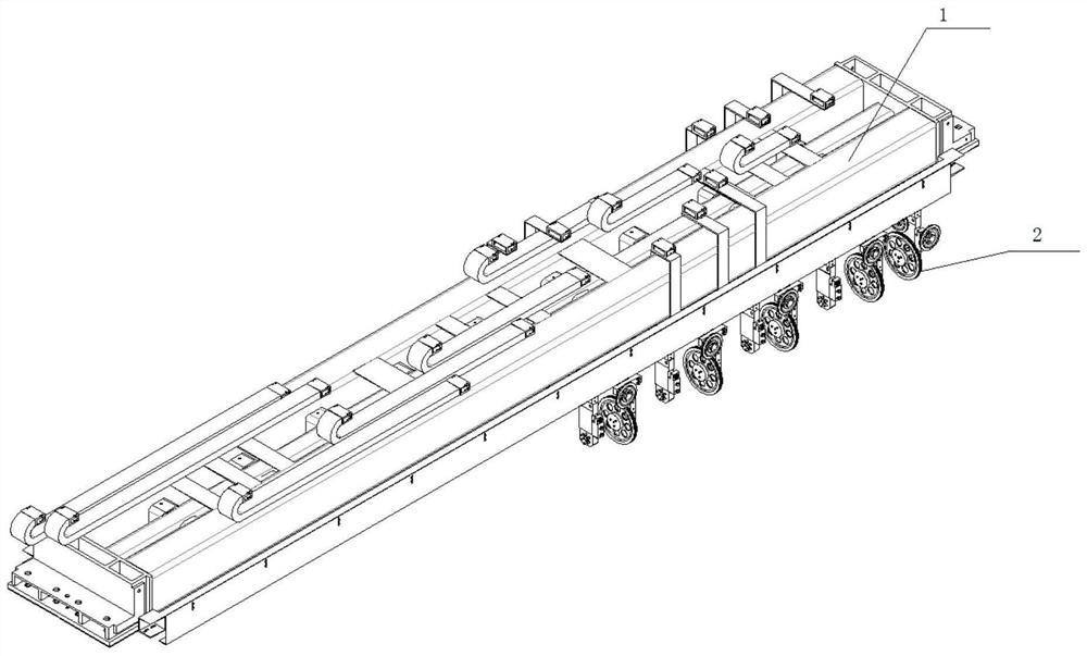
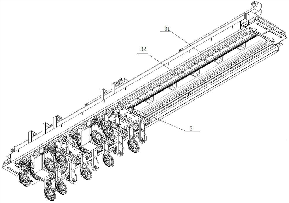
The invention provides a cut-off cross beam for a multi-head cut-off machine. The cut-off cross beam for the multi-head cut-off machine comprises a cross beam body, a plurality of cutting head devicesare arranged on the cross beam, and an axial movement driving device for driving the cutting head devices to move along the axial direction of the cross beam are arranged between the cutting head devices and the cross beam body; one diamond wire sequentially passes through the plurality of cutting head devices, a cutting line segment is formed between the two cutting wheels of each cutting head device, and the extending direction of the cutting line segments is perpendicular to the axial direction of the cross beam body; and in the plurality of cutting head devices, the cutting wheel in at least one cutting head device is connected with a cutting motor. According to the cut-off cross beam for the multi-head cut-off machine, the plurality of cutting head devices are adopted, one silicon rod can be cut into a plurality of silicon rod sections at a time, the machining efficiency is improved, each cutting head device can move in the axial direction of the cross beam through the axial movement driving device, and therefore the cutting position and the length of the cut silicon rod sections can be adjusted conveniently.

Description

Technical field [0001] The invention relates to the technical field of silicon rod cutting, in particular to a cutting beam for a multi-head cutting machine. Background technique [0002] The existing cutting machine has a cutting head, the cutting efficiency is low, and then multiple cutting heads are added to cut the silicon rod, which can cut the silicon rod at one time and cut the silicon rod into multiple sections. However, the existing multi-head cutting machine has many Each cutting head adopts a fixed method, and can only cut silicon rod segments of the same specification length each time, and the application range is narrow. Moreover, each cutting head on the existing multi-head cutting machine has a cutting motor, which is a serious waste. Summary of the invention [0003] According to the above technical problems, a cutting beam for a multi-head cutting machine is provided. [0004] The technical means adopted by the present invention are as follows: [0005] A cutting be...

Claims


Application Information

Patent Timeline
Patent Type & Authority Applications(China)
IPC IPC(8): B28D5/04B28D7/00
CPCB28D5/0058B28D5/0064B28D5/045
Inventor 马云鹏刘旭刘珊麟
Owner DALIAN LIANCHENG NUMERICAL CONTROL MACHINE
Learn More