Unlock instant, AI-driven research and patent intelligence for your innovation.

Automatic clamping and detecting device for injection molding insert

A detection device and insert technology, applied in coating and other directions, can solve the problems of poor product consistency, small operating space, poor structural strength, etc., to ensure production consistency and quality stability, reduce labor costs, and production efficiency. high effect

Pending Publication Date: 2020-11-17
常青智能科技(天津)有限公司
View PDF0 Cites 0 Cited by
  • Summary
  • Abstract
  • Description
  • Claims
  • Application Information

AI Technical Summary

Problems solved by technology

[0003] At present, most of the injection molding industry adopts the traditional insert installation method, that is, manual hanging and placing the insert into the injection mold. The installation efficiency and quality often depend on the operator's familiarity with the injection mold and the level of operating skills. However, there are many types and sizes of inserts. For example, some metal inserts are small sheet metal bending parts with small operating space and poor structural strength; the installation position of some inserts in the mold Special, manual operation is inconvenient, these situations have caused great difficulty for manual placement; moreover, a large number of manual participation will also result in poor product consistency, poor stability, and low efficiency. In addition, manual placement requires operators to frequently enter and exit the injection molding machine There are certain safety risks in the region; while automated production can reduce manual repetitive physical labor and reduce safety risks, the biggest advantage is the standardization of the production process, which can effectively ensure the consistency and stability of product quality and high production efficiency.

Method used


Image

  • Automatic clamping and detecting device for injection molding insert
  • Automatic clamping and detecting device for injection molding insert
  • Automatic clamping and detecting device for injection molding insert

Examples


Embodiment Construction

[0031] In order to make the object, technical solution and advantages of the present invention more clear and understandable, the present invention will be further described in detail below in conjunction with the accompanying drawings and embodiments.

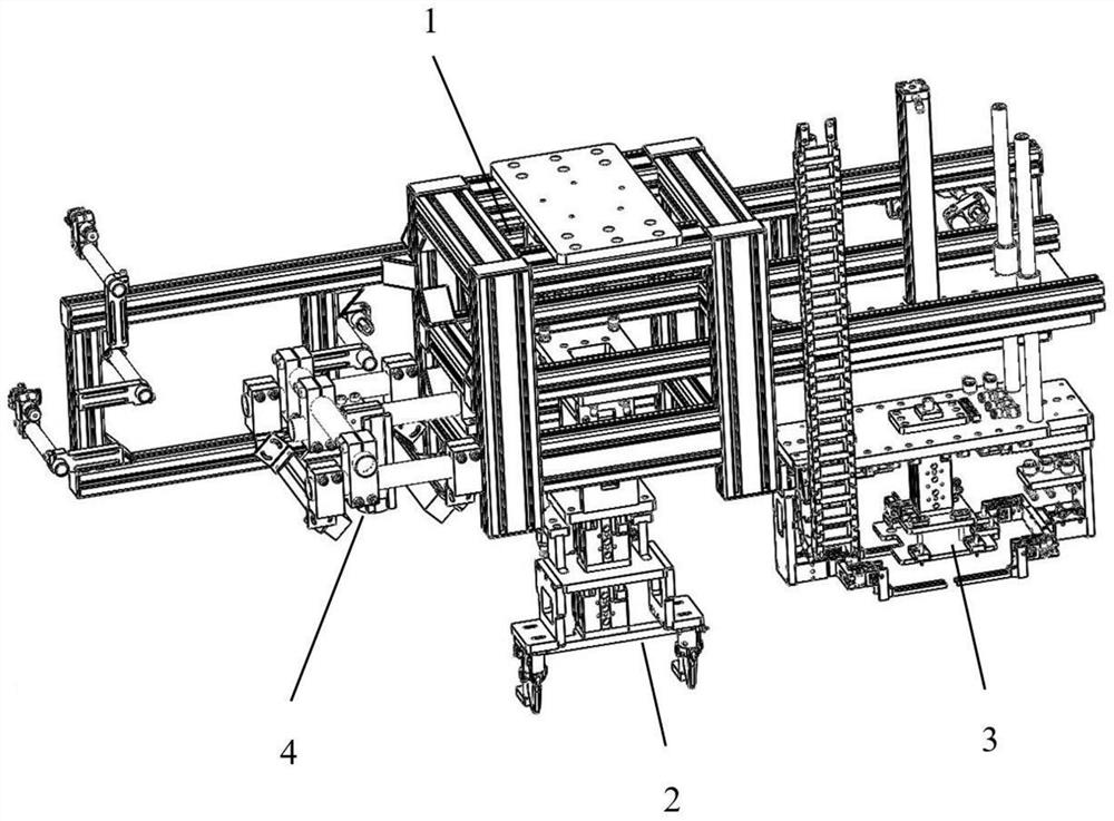
[0032] Such as Figures 1 to 16 As shown, the present invention provides an automatic clamping and testing device for injection molded inserts, including: a main body frame 1, a first clamping mechanism 2, a second clamping mechanism 3 installed on the main frame 1 and visual inspection Mechanism 4, the main frame 1 is spliced ​​by profiles and corner pieces, the upper end of the main frame 1 is connected to the robot, the first clamping mechanism 2 and the second clamping mechanism 3 are installed side by side on the Below the main frame 1, the first clamping mechanism 2 is used to clamp metal inserts, the second clamping mechanism 3 is used to clamp non-metallic mesh inserts, and the visual inspection mechanism 4 is used to ...


PUM


Abstract

The invention discloses an automatic clamping and detecting device for an injection molding insert. The automatic clamping and detecting device comprises a main body frame, a first clamping mechanism,a second clamping mechanism and a visual detection mechanism, the first clamping mechanism, the second clamping mechanism and the visual detection mechanism are installed on the main body frame, themain body frame is formed by splicing profiles and corner fittings, the main body frame is connected with a robot, the first clamping mechanism is used for automatically clamping a metal insert, the second clamping mechanism is used for automatically clamping a non-metal screen cloth insert, and the visual detection mechanism is used for detecting whether the insert is mounted qualified or not. According to the automatic clamping and detecting device, through cooperation with the robot, automatic clamping and installation detection of the injection molding product insert are achieved, a traditional manual installation mode is effectively replaced, the labor cost is reduced for enterprises, automatic and standardized production is achieved, the production consistency and quality stability of products are effectively guaranteed, and the production efficiency and safety are high.

Description

technical field [0001] The invention relates to the field of automation equipment, in particular to an automatic clamping and testing device for injection molding inserts. Background technique [0002] Automotive interior injection molding products are often inlaid with various inserts, including some special-shaped metal inserts or regular-shaped, flat non-metallic inserts. Before injection molding, the inserts need to be pre-installed on the corresponding positions on the injection mold. , and then close the mold for injection molding; the assembly efficiency and accuracy of inserts directly affect the production efficiency and quality stability of injection molded products. Therefore, to achieve fast, efficient, and high-precision insert installation is the goal that the entire injection molding industry has been pursuing. [0003] At present, most of the injection molding industry adopts the traditional insert installation method, that is, manual hanging and placing the ...

Claims


Application Information

Patent Timeline
IPC IPC(8): B29C45/14B29C45/76B29C45/42
CPCB29C45/14008B29C45/42B29C45/76B29C2945/76294
Inventor 邵月华刘志勇薛斐李冬喆李鹏
Owner 常青智能科技(天津)有限公司
Features
  • R&D
  • Intellectual Property
  • Life Sciences
  • Materials
  • Tech Scout
  • Unparalleled Data Quality
  • Higher Quality Content
  • 60% Fewer Hallucinations
Learn More