Paying-off device for high-voltage power transmission line

A technology of high-voltage transmission lines and pay-off devices, which is applied in the directions of transportation and packaging, cable laying equipment, thin material processing, etc., can solve the problems of high physical exertion, improve applicability, save time for replacing pay-off devices, and improve The effect of convenience

Active Publication Date: 2020-11-17
GUIZHOU POWER GRID CO LTD
View PDF11 Cites 0 Cited by
  • Summary
  • Abstract
  • Description
  • Claims
  • Application Information

AI Technical Summary

Problems solved by technology

[0004] The purpose of the present invention is to provide a high-voltage power transmission line pay-off device to solve the problems of fast rotation of the cable reel and large physical exertion in the above-mentioned background technology.

Method used


Image

  • Paying-off device for high-voltage power transmission line
  • Paying-off device for high-voltage power transmission line
  • Paying-off device for high-voltage power transmission line

Examples


Embodiment Construction

[0023] The following will clearly and completely describe the technical solutions in the embodiments of the present invention with reference to the accompanying drawings in the embodiments of the present invention. Obviously, the described embodiments are only some, not all, embodiments of the present invention. Based on the embodiments of the present invention, all other embodiments obtained by persons of ordinary skill in the art without making creative efforts belong to the protection scope of the present invention.

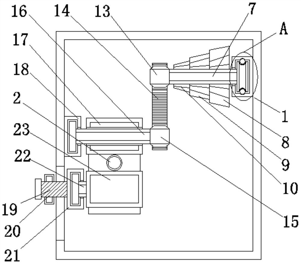
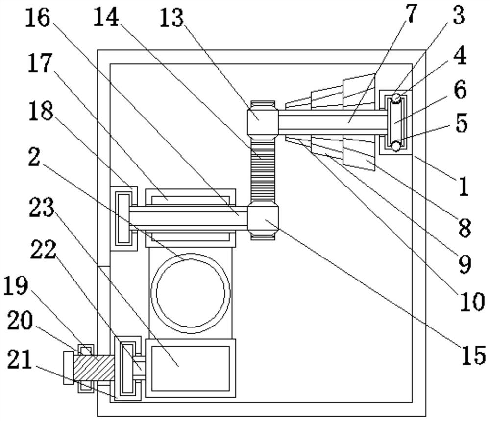
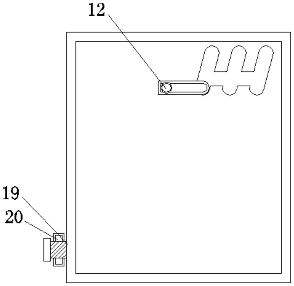
[0024] see Figure 1-6 , an embodiment provided by the present invention:

[0025] A wire releasing device for a high-voltage transmission line, comprising a housing 1 and a wire body 2, the housing 1 is provided with a wire body 2, the inner wall of the upper end of the housing 1 is welded with a rotating shaft groove 3, and the rotating shaft groove 3 passes through the rotating device and the first rotating rod 7 The connecting and rotating device includes...


PUM


Abstract

The invention discloses a paying-off device for a high-voltage power transmission line. The paying-off device comprises a shell and a wire body, wherein a rotating shaft groove is welded on the innerwall of the upper end of the shell, and the rotating shaft groove is connected with a first rotating rod through a rotating device; the first rotating rod is connected with a second rotating rod through a transmission device, and the second rotating rod penetrates through the middle of a first roller; and a limiting device is arranged on the surface of the left side of the lower end of the shell,and a second limiting groove is welded on the right side of the limiting device. According to the paying-off device, a first conical wheel, a second conical wheel, a third conical wheel, a fourth conical wheel, a rotating handle, the first roller and a second roller are arranged, the rotating handle is rotated, and the wire body is paid off by utilizing the friction force generated by the first roller and the second roller, so that the purpose of paying off the wire body by rotating the rotating handle is achieved, the problem of physical exertion due to the fact that a cable reel needs to bequickly rotated during rapid paying-off is solved, and the convenience of the paying-off device is improved.

Description

technical field [0001] The invention relates to the technical field of pay-off devices, in particular to a pay-off device for high-voltage transmission lines. Background technique [0002] When laying high-voltage transmission lines, two methods of cable transmission lines and overhead transmission lines are used. When using cable transmission lines, the cables need to be buried underground. Generally, high-voltage transmission lines are used to pay off the cables. , to avoid the problem that the cable is wound on the cable reel, the existing pay-off device for high-voltage transmission lines can basically meet the needs of daily use, but there are still some deficiencies that need to be improved. [0003] In the actual application process, the existing pay-off device for high-voltage transmission lines is generally installed on the cable reel. By rotating the cable reel, the cable is paid out through the pay-off device. Because the pay-off speed and the rotating cable The ...

Claims


Application Information

Patent Timeline
Patent Type & Authority Applications(China)
IPC IPC(8): B65H49/32B65H49/30H02G1/06
CPCB65H49/32B65H49/30H02G1/06B65H2701/34
Inventor 赵良文黄钰锡陈凤翔杨刘贵王斌冯文斌凌志
Owner GUIZHOU POWER GRID CO LTD
Why Eureka
Try Eureka