Sliding-preventing method and sliding-preventing hydraulic control system for traveling device

A technology of hydraulic control system and traveling device, which is applied in transmission device control, fluid pressure actuation system components, fluid pressure actuation device, etc. It can solve problems such as poor accuracy, potential safety hazards, difficult mechanical zero point of harvester, etc., and achieve High safety effect

Pending Publication Date: 2020-11-17
LOVOL HEAVY IND CO LTD
View PDF0 Cites 4 Cited by
  • Summary
  • Abstract
  • Description
  • Claims
  • Application Information

AI Technical Summary

Problems solved by technology
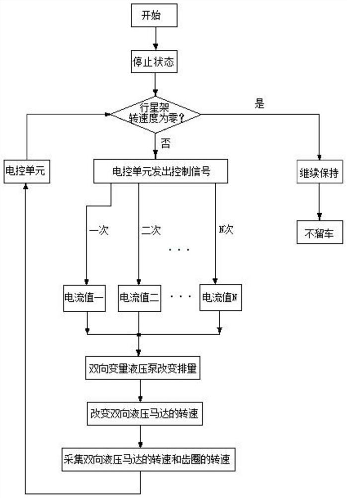
However, with the accumulation of use of the plunger pump and plunger motor in the hydraulic system of the existing harvester, the volumetric efficiency of the plunger pump and the plunger motor will change accordingly in different life periods and at different speeds of the prime mover. , and the existing plunger pump controls the displacement of the plunger pump through manual adjustment, and the accuracy of manually adjusting the displacement of the plunger pump to a specific displacement is poor, so it is difficult for the existing harvester to accurately reach the mechanical zero point , so that the harvester rolls away at different life periods and at different speeds of the prime mover, which poses a safety hazard. Moreover, other traveling devices controlled by hydraulic drive also have the same technical problems as above.

Method used


Image

  • Sliding-preventing method and sliding-preventing hydraulic control system for traveling device
  • Sliding-preventing method and sliding-preventing hydraulic control system for traveling device
  • Sliding-preventing method and sliding-preventing hydraulic control system for traveling device

Examples


Embodiment Construction

[0053] In order to make the purpose, technical solution and advantages of the present application clearer, the implementation manners of the present application will be further described in detail below in conjunction with the accompanying drawings.

[0054]In order to understand the above-mentioned purpose, features and advantages of the present invention more clearly, the present invention will be described in detail below in conjunction with the accompanying drawings and specific embodiments. It should be noted that, in the case of no conflict, the embodiments of the present application and the features in the embodiments can be combined with each other.

[0055] In the following description, many specific details are set forth in order to fully understand the present invention. However, the present invention can also be implemented in other ways different from those described here. Therefore, the protection scope of the present invention is not limited by the specific detai...


PUM


Abstract

The invention discloses a sliding-preventing method and sliding-preventing hydraulic control system for a traveling device, and belongs to the technical field of hydraulic control systems. The sliding-preventing method for the traveling device includes the following steps that the hydraulic control system is arranged on the traveling device, the hydraulic control system comprises a hydraulic mainoil way, a bidirectional variable hydraulic pump, a bidirectional hydraulic motor, an electric control unit and a planet gear transmission mechanism, the planet gear transmission mechanism comprises agear ring, a sun gear, a planet gear and a planet carrier, and the gear ring, the sun gear and the planet carrier are arranged coaxially and rotationally; when the traveling device stops, the electric control unit collects the rotating speed of the bidirectional hydraulic motor and the rotating speed of the gear ring and automatically calculates the output rotating speed of the planet carrier, and if the output rotating speed of the planet carrier is not zero, the electric control unit sends a control signal to the bidirectional variable hydraulic pump to change the displacement of the bidirectional variable hydraulic pump until the output rotating speed of the planet carrier is zero. According to the sliding-preventing method for the traveling device, the mechanical zero point can be accurately controlled, and sliding of the traveling device can be effectively prevented.

Description

technical field [0001] The invention relates to the technical field of hydraulic control systems, in particular to a method for anti-rolling of a traveling device and an anti-rolling hydraulic control system. Background technique [0002] The harvester is an important equipment in agricultural production. It is mainly used to harvest wheat, corn, rice and other crops. Among them, the harvester driven by the hydraulic system can realize stepless speed regulation and is widely used. In addition, the harvester maintains In the stopped state, the output speed of the planet carrier needs to be zero at this time, and the sun gear needs to output a specific speed to balance the speed of the ring gear. Specifically, the plunger pump drives the sun gear to rotate in the opposite direction to the ring gear. Rotating at a certain speed, the sun gear interacts with the ring gear to make the output speed of the planetary carrier zero. At this time, the plunger pump needs to run at a spec...

Claims


Application Information

Patent Timeline
Patent Type & Authority Applications(China)
IPC IPC(8): F15B11/08F15B15/18F15B13/04F15B21/041F16H61/40A01D41/12
CPCA01D41/12F15B11/08F15B13/0401F15B15/18F15B21/041F16H61/4035
Inventor 武小伟白永安杨述庆刘佳刘鑫张建胡德利刘媛媛张义顺
Owner LOVOL HEAVY IND CO LTD
Why Eureka
Try Eureka