
Noise-removing laminating machine

A laminating machine, noise technology, applied in nonlinear optics, instruments, optics, etc., can solve problems such as high noise in mechanical operation, and achieve the effect of avoiding safety problems

Pending Publication Date: 2020-11-17
深圳市合力泰光电有限公司
View PDF0 Cites 0 Cited by
  • Summary
  • Abstract
  • Description
  • Claims
  • Application Information

AI Technical Summary

Problems solved by technology

[0003] In the prior art, during the production and processing process of the conventional laminating machine, the mechanical operation noise is relatively large, and the sound insulation of the material is also difficult to solve the sound insulation problem of the wiring connection position

Method used


Image

  • Noise-removing laminating machine
  • Noise-removing laminating machine
  • Noise-removing laminating machine

Examples


Embodiment 1

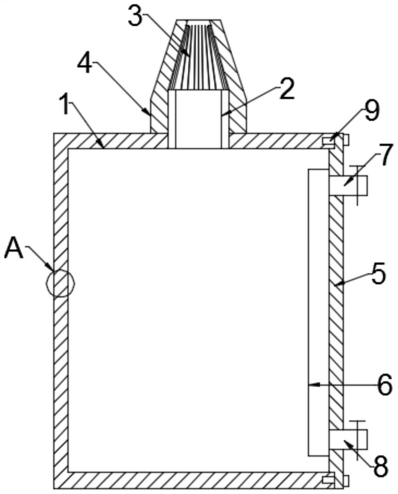
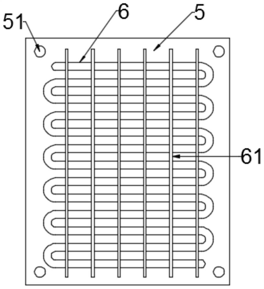
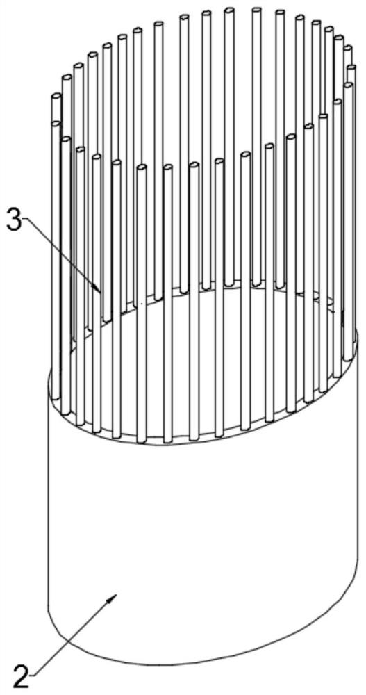
[0023] see Figure 1~3 , in an embodiment of the present invention, a noise-removing laminating machine includes a machine body 1, an access panel 5 is installed on one side of the body 1 through connecting bolts 9, and the access panel 5 is installed on the side of the body 1 There is a heat exchange type heat dissipation mechanism, the upper end of the body 1 is connected with a wiring tube 2, the wiring tube 2 is assembled and connected with a limit sleeve 4, and the side wall of the body 1 and the inspection panel 5 is embedded. There is an interlayer 10, and the interlayer 10 is filled with a sound-absorbing interlayer.

[0024] Mounting holes 51 are provided through the four top corners of the access panel 5 , and the mounting holes 51 are movably fitted with the connecting bolts 9 .

[0025] The heat exchange type heat dissipation mechanism includes a heat dissipation pipe 6, and the heat dissipation pipe 6 is attached to the side of the inspection panel 5. The periphe...

Embodiment 2

[0030] see Figure 4 , in the embodiment of the present invention, a kind of noise-removing laminating machine, on the basis of embodiment 1, described sound-absorbing interlayer comprises filling inner core 12, and described filling inner core 12 is the foam plate of honeycomb structure, and described The filling inner core 12 is filled and arranged in the interlayer 10, so that the weight of the device shell can be reduced and the noise reduction effect can be improved at the same time.

[0031] The interlayer 10 is also fixedly connected with a reinforcing plate 11, the reinforcing plate 11 is a continuously bent aluminum alloy plate, and the bent corners of the reinforcing plate 11 are respectively connected to the two side walls in the interlayer 10 to reinforce The arrangement of the plate 11 can support the interlayer 10 to improve the structural stability of the machine body 1, which is safer and more practical in use.

[0032] The standard parts used in the present i...


PUM


Abstract

The invention discloses a noise-removing laminating machine which comprises a machine body, an overhauling plate is installed on one side of the machine body through a connecting bolt, a heat exchangetype heat dissipation mechanism is installed on the side face, located in the machine body, of the overhauling plate, a wiring pipe is connected to the upper end of the machine body in a penetratingmode, and a limiting sleeve is assembled and connected to the wiring pipe; interlayers are embedded in the side walls of the machine body and the maintenance plate, and the interlayers are filled withsilencing interlayers. According to the noise-removing laminating machine, the wiring pipe is matched with the limiting sleeve to limit and fix the circuit and overcome the sound insulation problem of the circuit leading-out part, and the heat exchange type heat dissipation structure can solve the internal isolation problem caused by the sound insulation of the silencing interlayer, so that the safety problem can be avoided.

Description

technical field [0001] The invention relates to the technical field of laminating machines, in particular to a laminating machine for eliminating noise. Background technique [0002] The laminating machine is mainly designed for the production characteristics of small displays and small touch components. It is one of the necessary equipment for the production of liquid crystal displays. It is used in the post-production process of liquid crystal displays. Attaching polarizers at an angle, the laminating machine is mainly designed for the production characteristics of small displays and small touch components. While improving the intensity of manual labor, it also gets rid of the excessive dependence on the proficiency of personnel. [0003] In the prior art, during the production and processing process of the conventional laminating machine, the mechanical operation noise is relatively large, and the sound insulation of the material is also difficult to solve the sound insu...

Claims


Application Information

Patent Timeline
Patent Type & Authority Applications(China)
IPC IPC(8): G02F1/13G02F1/1335
CPCG02F1/1303G02F1/133528
Inventor 郭利艳刘少林
Owner 深圳市合力泰光电有限公司
Learn More