
Flow control device

A technology of flow control device and flow area, which is applied in the direction of flow control without auxiliary power, can solve the problems of low reliability, large flow, and high requirements for valve core materials, and achieve high reliability, simple structure of the device, and convenient processing. Effect

Active Publication Date: 2020-11-17
GUIZHOU HONGLIN MACHINERY
View PDF10 Cites 0 Cited by
  • Summary
  • Abstract
  • Description
  • Claims
  • Application Information

AI Technical Summary

Problems solved by technology

[0002]Usually, when the temperature changes, the viscosity of the fluid medium will be significantly affected, further affecting the product flow rate. Currently, the existing flow control devices on the domestic market , its flow is mostly affected by temperature and viscosity. The higher the temperature of the liquid, the smaller the viscosity and the greater the flow; only a small part of the flow is not affected by temperature and viscosity changes. The principle of temperature and viscosity is that the internal valve core adopts temperature-sensitive The material controls the size of the flow channel, thereby controlling the flow rate, but the disadvantages of this structure are that the requirements for the valve core material are high, the design and processing are difficult, and the reliability is low

Method used


Image

  • Flow control device
  • Flow control device
  • Flow control device

Examples


Embodiment Construction

[0018] The present invention will be further described below in conjunction with the drawings and embodiments, but it is not a basis for limiting the present invention.

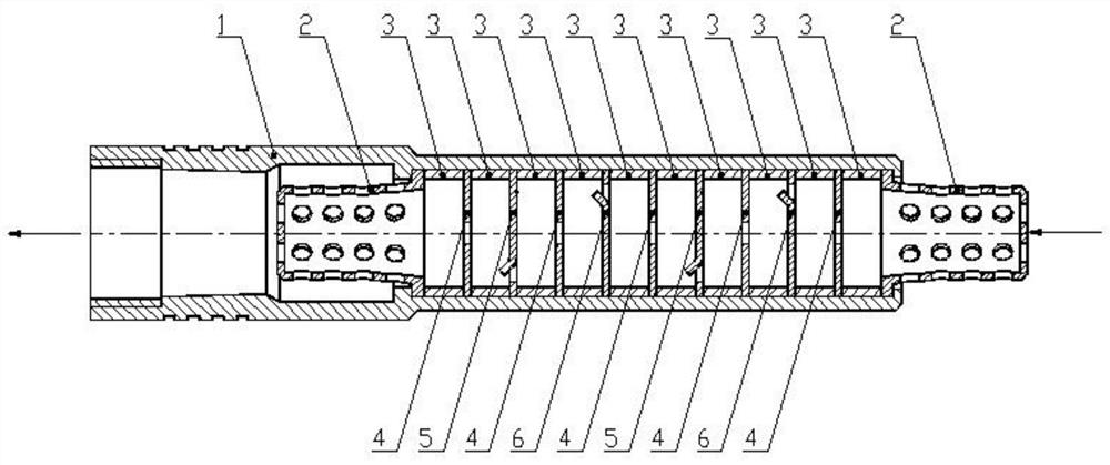
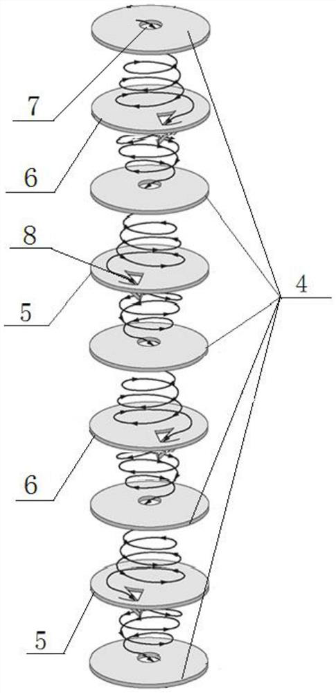
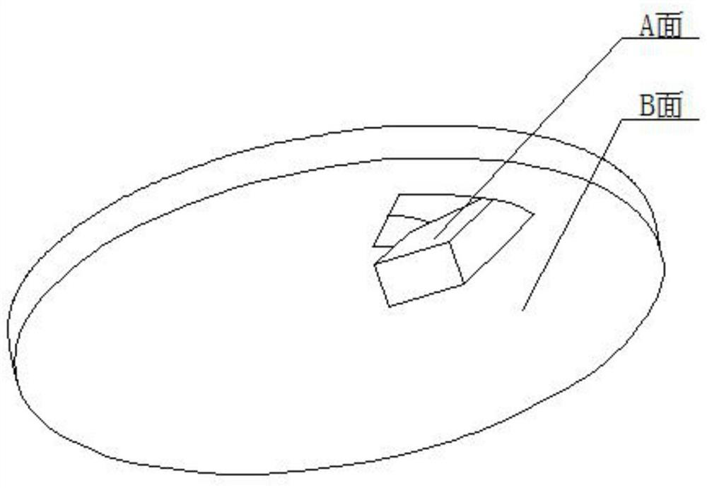
[0019] Embodiment of the present invention: a flow control device, as attached Figure 1-4 As shown, it includes a housing 1 with a hollow inside and open at both ends. The inside of the housing 1 is sequentially and evenly spaced from the inlet end to the outlet end and is repeatedly provided with a center disk 4, a left rotating disk 6, a center disk 4, and a right rotating disk. 5; Or the central disk 4, the right rotating disk 5, the center disk 4 and the left rotating disk 6 are arranged sequentially, at intervals, and repeatedly, and the center disk 4 is at the end. As attached figure 1 As shown, the device housing 1 of this embodiment is sequentially and evenly spaced from the inlet end to the outlet end with a center disk 4, a left rotating disk 6, a center disk 4, a right rotating disk 5, a center disk ...


PUM


Abstract

The present invention discloses a flow control device, which comprises a shell that is hollow inside and provided with openings in the two ends; a center disc, a left rotating disc, a center disc anda right rotating disc are sequentially and repeatedly arranged in the shell from the inlet end to the outlet end at intervals, or the center disc, the right-handed rotation disc, the center disc and the left rotation disc are arranged sequentially and repeatedly at intervals; wherein the center disc is arranged at the tail end, a center hole is formed in the middle of the center disc, and rotationgrooves with opposite opening directions are formed in the edges of disc bodies of the right-handed rotation disc and the left rotation disc. The device is simple in structure, convenient to machine,high in reliability and provided with a viscosity compensation structure, and the passing flow is basically kept constant under the same pressure difference no matter how the external temperature changes.

Description

Technical field [0001] The invention relates to a flow control device, in particular to a flow control device that can realize that the flow is not affected by temperature and viscosity. Background technique [0002] Under normal circumstances, when the temperature changes, it will have a significant impact on the viscosity of the fluid medium, which will further affect the product flow. The current flow control devices on the domestic market are mostly affected by temperature and viscosity, and the higher the liquid temperature , The smaller the viscosity, the greater the flow; only a small part of the flow is not affected by temperature and viscosity changes. The principle of temperature and viscosity is that the internal valve core uses temperature-sensitive materials to control the size of the flow channel, thereby controlling the flow. However, this structure has disadvantages In order to have higher requirements on the valve core material, the design and processing are diff...

Claims


Application Information

Patent Timeline
Patent Type & Authority Applications(China)
IPC IPC(8): G05D7/01
CPCG05D7/01
Inventor 何少健曾祥尧冉林张庆军赵晶
Owner GUIZHOU HONGLIN MACHINERY
Learn More