Battery liquid cooling plate structure and automobile battery

A battery liquid and liquid cold plate technology, which is applied to secondary batteries, circuits, electrical components, etc., can solve the problems of poor cooling and heat dissipation effect, heavy weight, and overall thickness angle of the cold liquid plate and battery, and improve cooling and heat dissipation Performance, prevention of a sharp rise in temperature, and the effect of reducing the overall thickness

Inactive Publication Date: 2020-11-17
东风时代(武汉)电池系统有限公司
View PDF6 Cites 6 Cited by
  • Summary
  • Abstract
  • Description
  • Claims
  • Application Information

AI Technical Summary

Problems solved by technology

[0004] In the related art, the battery liquid cold plate generally includes a bottom plate, an upper plate and a plurality of harmonica tubes, and the harmonica tubes are fixed side by side on the bottom plate; but the battery liquid cold plate has the following problems: 1. The overall thickness angle of the battery liquid cold plate , the quality is heavy; 2. The battery is installed on the upper plate, and the cooling liquid enters the flow channel in the upper plate from the inlet port on the upper plate, and then flows into each harmonica tube, and the harmonica tube cools and dissipates the battery through the upper plate, so the battery The cold liquid plate needs to pass through the upper plate to cool and dissipate heat, and the cooling effect between the cold liquid plate and the battery is not good

Method used


Image

  • Battery liquid cooling plate structure and automobile battery
  • Battery liquid cooling plate structure and automobile battery
  • Battery liquid cooling plate structure and automobile battery

Examples


Embodiment Construction

[0023] In order to make the purpose, technical solutions and advantages of the embodiments of the present invention clearer, the technical solutions in the embodiments of the present invention will be clearly and completely described below in conjunction with the drawings in the embodiments of the present invention. Obviously, the described embodiments It is a part of embodiments of the present invention, but not all embodiments. Based on the embodiments of the present invention, all other embodiments obtained by persons of ordinary skill in the art without making creative efforts belong to the protection scope of the present invention.

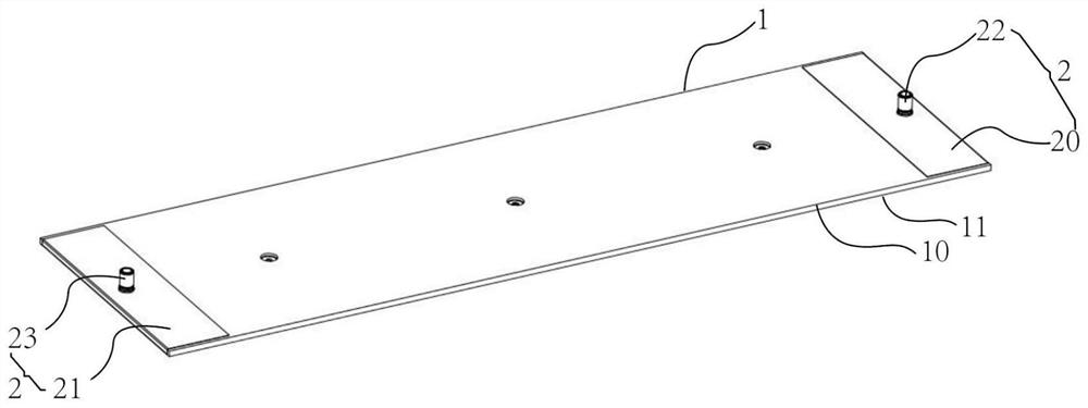
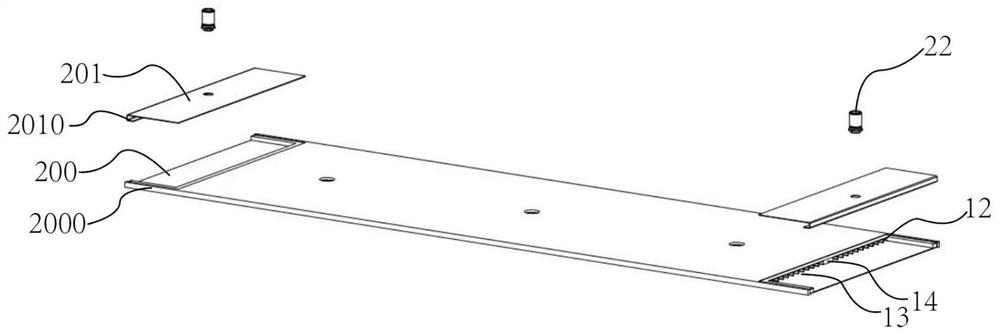
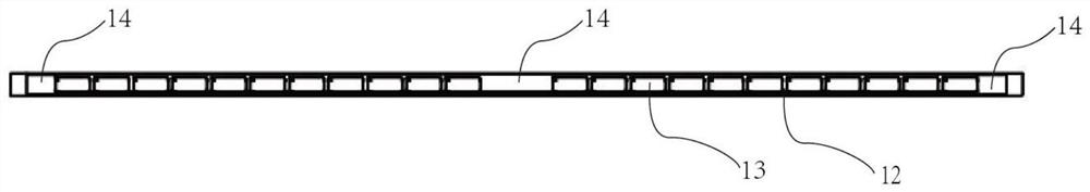
[0024] see figure 1 , figure 2 As shown; the embodiment of the present invention provides a battery liquid cooling plate structure, including a liquid cooling plate main body 1 and a liquid inlet and outlet structure 2, and the liquid cooling plate main body 1 includes an upper cooling plate 10 and a lower cooling plate 11 arranged side by ...


PUM


Abstract

The invention relates to a battery liquid cooling plate structure and an automobile battery. The battery liquid cooling plate structure comprises a liquid cooling plate main body and a liquid inlet and outlet structure. The liquid cooling plate main body comprises an upper cooling plate and a lower cooling plate arranged side by side up and down, a plurality of partition plate ribs arranged between the upper cooling plate and the lower cooling plate at intervals, and a cooling cavity between the upper cooling plate and the lower cooling plate is divided into a plurality of cooling flow channels by the plurality of partition plate ribs. The liquid inlet and outlet structure comprises a liquid inlet plate structure and a liquid outlet plate structure which are arranged at the two ends of theliquid cooling plate body respectively, a liquid inlet cavity communicated with one end of the cooling flow channel is formed in the liquid inlet plate structure, and a liquid outlet cavity communicated with the other end of the cooling flow channel is formed in the liquid outlet plate structure; a liquid inlet head communicated with the liquid inlet cavity is arranged on the liquid inlet plate structure, and a liquid outlet head communicated with the liquid outlet cavity is arranged on the liquid outlet plate structure. According to the present invention, the processing technology of the battery liquid cooling plate is simplified, so that the liquid cooling plate meets the design requirement of light weight, and meanwhile, the cooling and heat dissipation performance of the liquid cooling plate is improved.

Description

technical field [0001] The invention relates to the technical field of battery cooling, in particular to a battery liquid cold plate structure and an automobile battery. Background technique [0002] Batteries are the core components of power vehicles. In terms of the manufacturing cost of pure electric vehicles, batteries also account for the highest proportion. The industry believes that the biggest problems of electric vehicles at present are price and pure electric cruising range. The main solutions to these two problems In addition to improving the energy density of the battery pack, there are also standardization and lightweighting. Standardization refers to the standardization of core components such as battery modules and motors, while lightweighting refers to reducing the weight of the vehicle without reducing the safety factor of the vehicle. Weight reduction for large components. This is the main direction of the development of electric vehicle technology in the ...

Claims


Application Information

Patent Timeline
Patent Type & Authority Applications(China)
IPC IPC(8): H01M10/613H01M10/625H01M10/6554H01M10/6556H01M10/6567
CPCH01M10/613H01M10/625H01M10/6554H01M10/6556H01M10/6567Y02E60/10
Inventor 王颖徐红宝
Owner 东风时代(武汉)电池系统有限公司
Why Eureka
Try Eureka