Supercharge Your Innovation With Domain-Expert AI Agents!

Installation device and installation method

A technology for installation devices and installation methods, which is applied in the direction of chucks, manipulators, electrical components, etc., can solve the problems of increased manufacturing costs and complex structures, and achieve the effect of suppressing manufacturing costs

Active Publication Date: 2022-03-11
KAWASAKI HEAVY IND LTD
View PDF9 Cites 0 Cited by
  • Summary
  • Abstract
  • Description
  • Claims
  • Application Information

AI Technical Summary

Problems solved by technology

Therefore, the structure for identifying the positions of the leads of the held electronic components and mounting the electronic components on the substrate becomes complicated, and the manufacturing cost of the device may increase.

Method used


Image

  • Installation device and installation method
  • Installation device and installation method
  • Installation device and installation method

Examples


no. 1 approach

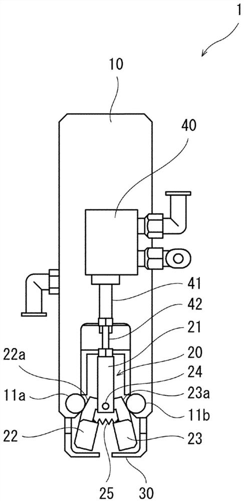
[0048] figure 1 It is a front view of the mounting device 1 according to the first embodiment of the present invention. The mounting device 1 includes a main body 10 , a holding portion 20 for holding an electronic component, and a regulating portion 30 for regulating the position of a lead wire in the electronic component.

[0049] In this embodiment, a resistor is used as an electronic component. The resistor has a resistor main body having resistance, and two lead wires are formed extending from the resistor main body. The two lead wires are provided so as to extend laterally from both side portions of the resistor main body. In addition, the two lead wires are respectively bent in the same direction at positions lateral to the main body. Therefore, the resistor can be mounted on the board by inserting together the lead wires bent in the same direction and extending in the same direction into the insertion opening formed in the board.

[0050] In addition, in this Embod...


PUM


Abstract

The present invention provides a mounting device for mounting electronic components on a substrate with a simple structure. The mounting device includes: a holding unit that holds the electronic component; and a regulating unit that regulates the radial position of the leads in the electronic component. The restricting portion can restrict the position of the first portion in the lead wire, and can restrict the position of the second portion in the lead wire that is farther from the holding portion than the first portion. By relatively moving the holding part and the restricting part in the state where the holding part holds the electronic component, the restricting part is in the position for restricting the position of the first part of the lead wire and the position for restricting the position of the second part of the lead wire. The location is restricted for moving between locations.

Description

technical field [0001] The present invention relates to a mounting device and a mounting method for mounting electronic components on a substrate. Background technique [0002] Conventionally, an apparatus for mounting electronic components on a substrate using a robot has been proposed. As an apparatus for mounting electronic components in this way, there is an apparatus disclosed in Patent Document 1. Patent Document 1 discloses a device that holds an electronic component, clamps a lead wire extending from the electronic component, inserts the clamped lead wire into an insertion hole provided in a substrate, and mounts the electronic component on a substrate. [0003] Patent Document 1: Japanese Patent Laid-Open No. 2015-95575 [0004] However, in the device disclosed in Patent Document 1, the clamped lead wire is inserted into the substrate as it is, and therefore a camera is used to detect the position of the held lead wire. The electronic part is photographed by a ca...

Claims


Application Information

Patent Timeline
Patent Type & Authority Patents(China)
IPC IPC(8): H05K13/04B25J15/08
CPCH05K13/0408H05K13/0421B25J15/0226H05K13/0812H05K13/0413H05K13/046B25J15/0028
Inventor 木村俊满
Owner KAWASAKI HEAVY IND LTD
Features
  • R&D
  • Intellectual Property
  • Life Sciences
  • Materials
  • Tech Scout
  • Unparalleled Data Quality
  • Higher Quality Content
  • 60% Fewer Hallucinations
Learn More