High-efficiency motor rotor grinding equipment and using method thereof

A motor rotor, high-efficiency technology, applied to grinding/polishing equipment, grinding devices, grinding machine tools, etc., can solve the problems of cumbersome operation, high motor rotor temperature, and low grinding efficiency, so as to increase the range of air outlet and prevent overheating too high effect

Active Publication Date: 2020-11-20
温岭中昊电机配件有限公司
View PDF14 Cites 1 Cited by
  • Summary
  • Abstract
  • Description
  • Claims
  • Application Information

AI Technical Summary

Problems solved by technology

[0003] At present, when producing motor rotors, it is often necessary to grind the motor rotors. The current grinding device still has the following deficiencies: 1. The current grinding device cannot grind all parts of the motor rotor at the same time, and the grinding efficiency is low; When the rotor is ground, the motor rotor cannot be cooled, and it is easy to cause the temperature of the motor rotor to be too high during the friction process; 3. When fixing the motor rotor, the operation is cumbersome and troublesome; therefore, to sum up the above problems, This technical solution proposes a high-efficiency motor rotor grinding equipment and its use method to solve the above-mentioned problems

Method used


Image

  • High-efficiency motor rotor grinding equipment and using method thereof
  • High-efficiency motor rotor grinding equipment and using method thereof
  • High-efficiency motor rotor grinding equipment and using method thereof

Examples


Embodiment 1

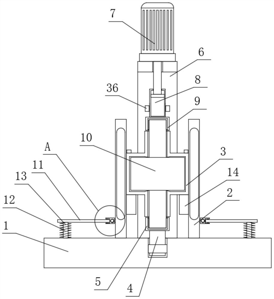
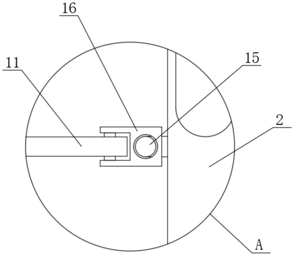
[0047] Embodiment one: if Figure 1-8 As shown, a high-efficiency motor rotor grinding equipment includes a base 1, two moving rings 2 are symmetrically slidably connected to the top of the base 1, and U-shaped grinding plates are clamped on the sides of the two moving rings 2 that are close to each other. 3. The top of the base 1 is rotatably connected with the support shaft 4 located between the two moving rings 2, the top of the support shaft 4 is fixedly installed with the support cover 5, and the motor rotor 10 is clamped inside the support cover 5, and the motor rotor 10 The top end extends to the top of the support cover 5, an L-shaped frame 6 is fixedly installed on one side of the top of the base 1, and a driving motor 7 is fixedly installed on the top of the L-shaped frame 6, and the output shaft of the driving motor 7 runs through the L-shaped frame 6 and is slidably connected There is a card cover 9, the top of the motor rotor 10 extends into the card cover 9 and i...

Embodiment 2

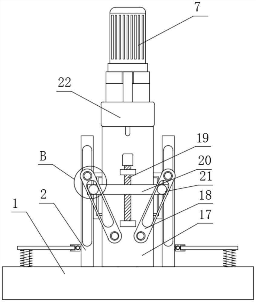
[0061] Embodiment two: if Figure 9-15 As shown, a high-efficiency motor rotor grinding equipment, the difference between this embodiment and Embodiment 1 is that: one side of the mounting plate 17 is rotatably connected with a mounting shaft 58 located in the fixed cover 37, and the mounting shaft 58 is located in the stepping Below the motor 47, the output shaft of the stepper motor 47 and one end of the installation shaft 58 are fixedly equipped with a synchronous wheel 48, and the two synchronous wheels 48 are driven and connected with the same synchronous belt 49, and the synchronous belt 49 moves the box 41 transmission connection , the other side of the moving box 41 is fixedly equipped with a slide bar 51, and a slip ring 52 is slidingly sleeved on the slide bar 51; 49 is fixedly connected, a support plate 44 is fixedly installed on one side of the fixed cover 37, and a rack 45 is fixedly installed on one side of the support plate 44, and a gear 46 is fixedly set on th...


PUM


Abstract

The invention discloses high-efficiency motor rotor grinding equipment and a using method thereof. The high-efficiency motor rotor grinding equipment comprises a base, wherein two moving rings are symmetrically and slidably connected to the top of the base, and U-shaped grinding plates are arranged on the sides, close to each other, of the two moving rings in a clamped mode; a supporting shaft located between the two moving rings is rotationally connected to the top of the base, a supporting cover is fixedly arranged at the top end of the supporting shaft, a motor rotor is arranged in the supporting cover in a clamped mode, and the top end of the motor rotor extends to the position above the supporting cover; and an L-shaped frame is fixedly arranged on one side of the top of the base, anda driving motor is fixedly arranged at the top of the L-shaped frame. According to the high-efficiency motor rotor grinding equipment and the using method thereof, the motor rotor can be convenientlypositioned and mounted, the motor rotor can be comprehensively ground, and the motor rotor can be synchronously cooled in the grinding process so that the situation that the motor rotor is damaged due to over-high temperature while being ground can be prevented.

Description

technical field [0001] The invention relates to the technical field of motor production, in particular to a high-efficiency motor rotor grinding device and a use method thereof. Background technique [0002] The motor rotor is the rotating part in the motor. The motor consists of two parts, the rotor and the stator, which are used to realize the conversion of electrical energy and mechanical energy and mechanical energy and electrical energy. The motor rotor is divided into motor rotor and generator rotor, and the motor rotor is divided into two types: inner rotor rotation mode and outer rotor rotation mode. The rotation mode of the inner rotor is that the core body in the middle of the motor is a rotating body, which outputs torque (referring to the motor) or receives energy (referring to the generator). The rotation mode of the outer rotor is to use the outer body of the motor as the rotating body, and different modes facilitate the application in various occasions. [...

Claims


Application Information

Patent Timeline
Patent Type & Authority Applications(China)
IPC IPC(8): B24B37/00B24B37/34B24B55/02B24B1/00
CPCB24B37/00B24B37/34B24B55/02B24B1/00H02K15/02
Inventor 曹祥安丁雪琴刘红
Owner 温岭中昊电机配件有限公司
Why Eureka
Try Eureka