Automatic sand blasting device for surface of large flat mechanical part

A technology for mechanical parts and sandblasting devices, which is applied to used abrasive treatment devices, abrasive jetting machine tools, abrasives, etc., can solve problems such as high technical requirements for operators, no sandblasting on the surface of parts, and safety threats for operators. To achieve the effect of uniform sandblasting, improved sandblasting efficiency, and improved operational safety

Inactive Publication Date: 2020-11-20
台州市凯规机械科技有限公司
View PDF0 Cites 2 Cited by
  • Summary
  • Abstract
  • Description
  • Claims
  • Application Information

AI Technical Summary

Problems solved by technology

[0002] Surface sandblasting refers to the process of cleaning and roughening the surface of the substrate by the impact of high-speed sand flow. At present, sandblasting on the surface of parts is mainly carried out manually. During the sandblasting operation, the high-speed and high-pressure sand flow poses a threat to the safety of operators. At the same time, sandblasting on the surface of parts requires a lot of technical requirements for operators. Manual sandblasting is prone to heavy spraying and missing spraying. At present, there are sandblasting devices for mechanical sandblasting, but there is almost no device for sandblasting on the surface of parts with large flat surfaces.

Method used


Image

  • Automatic sand blasting device for surface of large flat mechanical part
  • Automatic sand blasting device for surface of large flat mechanical part
  • Automatic sand blasting device for surface of large flat mechanical part

Examples


Embodiment Construction

[0017] All features disclosed in this specification, or steps in all methods or processes disclosed, may be combined in any manner, except for mutually exclusive features and / or steps.

[0018] Combine below Figure 1-7 The present invention is described in detail, and for convenience of description, the orientations mentioned below are now stipulated as follows: figure 1 The up, down, left, right, front and back directions of the projection relationship itself are the same.

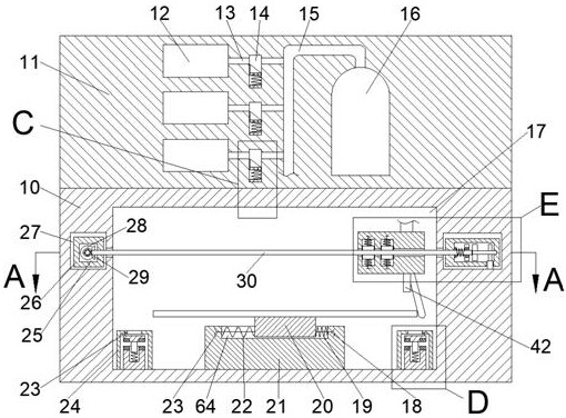
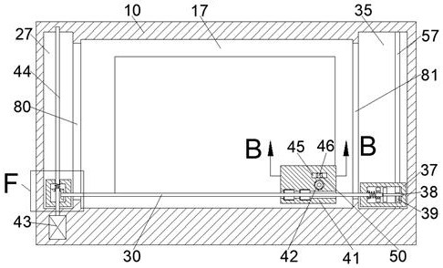
[0019] like Figure 1-7 As shown, a kind of automatic sandblasting device for the surface of large plane mechanical parts of the device of the present invention includes a main box body 10, and a sandblasting chamber 17 is arranged in the main box body 10, and the left side of the sandblasting chamber 17 communicates with A left shaft sliding chamber 80 is provided, the left side of the left shaft sliding chamber 80 is connected with a transmission box sliding chamber 27, and the right side of the sand...


PUM


Abstract

The invention discloses an automatic sand blasting device for the surface of a large flat mechanical part. The automatic sand blasting device comprises a main box, a sand blasting cavity is formed inthe main box, the left side of the sand blasting cavity is communicated with a left-axis sliding cavity, the left side of the left-axis sliding cavity is communicated with a transmission box sliding cavity, the right side of the sand blasting cavity is communicated with a right-axis sliding cavity, the right side of the right-axis sliding cavity is communicated with a stepping box sliding cavity,a transmission bevel gear box is in slidable and matched connection in the transmission box sliding cavity, and a transmission bevel gear cavity is arranged in the bevel gear box. According to the device, automatic sand blasting is conducted instead of manual sand blasting, the sand blasting efficiency is greatly improved, the harm, caused by the dust generated during sand blasting, to the human body is prevented, and the operation safety of operators is improved. Because sand blasting operation is carried out in the closed sand blasting cavity, the dust and waste gas generated during sand blasting cannot pollute the working environment of workers, and sand is more uniformly blasted to the surface of the part due to fixed-distance sand blasting, the problems of repeated blasting and blasting missing are solved, and the sand blasting effect is greatly improved.

Description

technical field [0001] The invention relates to the technical field of sandblasting equipment on the surface of parts, in particular to an automatic sandblasting device for the surface of large plane mechanical parts. Background technique [0002] Surface sandblasting refers to the process of cleaning and roughening the surface of the substrate by the impact of high-speed sand flow. At present, sandblasting on the surface of parts is mainly carried out manually. During the sandblasting operation, the high-speed and high-pressure sand flow poses a threat to the safety of operators. At the same time, sandblasting on the surface of parts requires a lot of technical requirements for operators. Manual sandblasting is prone to heavy spraying and missed spraying. At present, there are sandblasting devices for mechanical sandblasting, but there are almost no devices for sandblasting on the surface of parts with large flat surfaces. Contents of the invention [0003] Aiming at the ...

Claims


Application Information

Patent Timeline
Patent Type & Authority Applications(China)
IPC IPC(8): B24C3/00B24C9/00
CPCB24C3/00B24C9/00
Inventor 罗湘
Owner 台州市凯规机械科技有限公司
Why Eureka
Try Eureka