

Manufacturing device for hollow bricks
A technology for hollow bricks and equipment, applied in the direction of manufacturing tools, supply devices, forming conveyors, etc.
- Summary
- Abstract
- Description
- Claims
- Application Information
AI Technical Summary
Problems solved by technology
Method used
Image

Examples
Embodiment 1
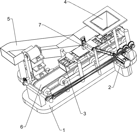
[0023] A kind of hollow brick making equipment, such as figure 1 As shown, it includes a base 1, a servo motor 2, a storage basket 3, a feeding basket 4, a slide plate 5, a transmission mechanism 6, a pressing mechanism 7, a third support column 8 and a fixed frame 9, and the top front of the right side of the base 1 There is a servo motor 2 on the side, and a transmission mechanism 6 is provided on the front side of the top of the base 1. The transmission mechanism 6 is connected with the output shaft of the servo motor 2. A storage basket 3 is placed on the parts of the transmission mechanism 6. The right front side of the top of the base 1 is uniformly arranged There are two third support columns 8, and a fixed frame 9 is connected between the tops of the third support columns 8, and a blanking basket 4 is placed in the middle of the fixed frame 9, a slide plate 5 is provided on the rear side of the top of the base 1, and the front middle of the top of the base 1 A pressing...
Embodiment 2
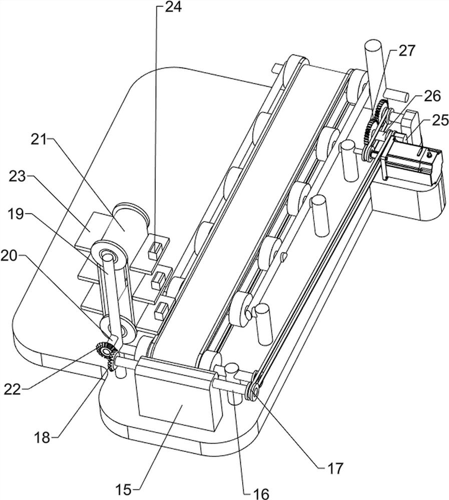
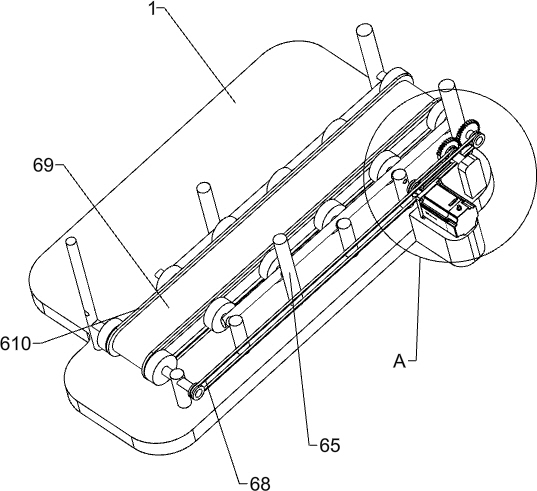
[0026] On the basis of Example 1, such as figure 2 , image 3 , Figure 4 and Figure 5 As shown, the transmission mechanism 6 includes a first fixed block 61, a first round shaft 62, a first transmission assembly 63, a first missing gear 64, a first support column 65, a second round shaft 66, a first gear 67, a first The second transmission assembly 68, the third transmission assembly 69 and the fixed bar 610, the base 1 top right front side is provided with the first fixed block 61, the first fixed block 61 is located on the right side of the servo motor 2, the rear part of the first fixed block 61 is rotatable The first round shaft 62 is connected, the first transmission assembly 63 is connected between the first round shaft 62 and the output shaft of the servo motor 2, the first missing gear 64 is arranged at the rear of the first round shaft 62, and the top of the base 1 is evenly arranged The first support column 65, the quantity of the first support column 65 is 12,...
Embodiment 3
[0031] On the basis of Example 2, such as Figure 6 and Figure 7 As shown, it also includes a third fixed block 10, a pull rod 11, an extension spring 12, a baffle plate 13 and a handle 14, and a third fixed block 10 is connected between the upper side of the first support column 65 on the right side, and the third fixed block The front and rear sides of 10 are slidably connected with a pull rod 11, a handle 14 is connected between the left part of the pull rod 11, and a stretch spring 12 is evenly connected between the right part of the handle 14 and the left part of the third fixed block 10, and the stretch spring 12 is evenly covered. On the pull rod 11, a baffle plate 13 is provided on the upper right side of the handle 14, and the baffle plate 13 cooperates with the blanking basket 4.
[0032] When people need to control the cutting of bricks, people first pour the bricks into the blanking frame, and when people need to make the bricks fall into the storage basket 3, pe...
PUM
 Abstract
Description
Claims
Application Information