Check patentability & draft patents in minutes with Patsnap Eureka AI!

Bionic fishtail propelling mechanism

A propulsion mechanism and fishtail technology, which is applied in the field of high-efficiency bionic fishtail propulsion mechanism, can solve the problems of low drive efficiency, inflexibility, and bulky volume, etc., and achieve the effects of improving drive efficiency, increasing control performance, and high control precision

Active Publication Date: 2020-11-20
ZHEJIANG UNIV
View PDF6 Cites 2 Cited by
  • Summary
  • Abstract
  • Description
  • Claims
  • Application Information

AI Technical Summary

Problems solved by technology

[0003] The existing bionic fishtail swing driving mechanism driven by mechanical structure generally has complex structure, large volume and high failure rate
The existing bionic fishtail drive mechanism using new smart materials has different problems for different smart materials: it is difficult to guarantee the temperature control accuracy when adjusting the temperature to realize the drive, and the voltage is as high as thousands of volts to realize the drive by adjusting the voltage. slow phase change
The existing bionic fishtail drive mechanism driven by wire traction, through the wire traction and combined with mechanical devices, has complex structure, large volume, and high difficulty in control
The existing bionic fishtail drive mechanism driven by hydraulic means needs to adopt a specific cavity structure, resulting in low drive hydraulic efficiency and requiring a large amount of liquid to drive
[0004] In short, the existing bionic fishtail swing driving mechanism generally has the defects of low driving efficiency, low driving accuracy, and insufficient flexibility.

Method used


Image

  • Bionic fishtail propelling mechanism
  • Bionic fishtail propelling mechanism
  • Bionic fishtail propelling mechanism

Examples


Embodiment Construction

[0056] The present invention will be further described below in conjunction with accompanying drawing:

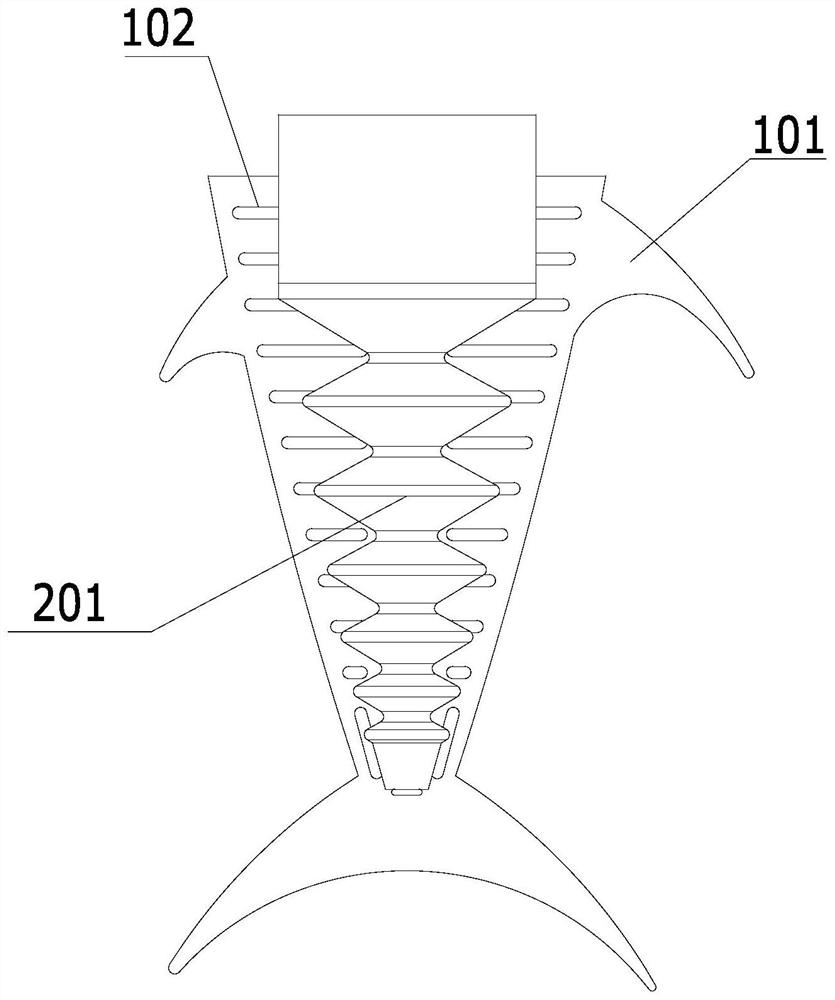
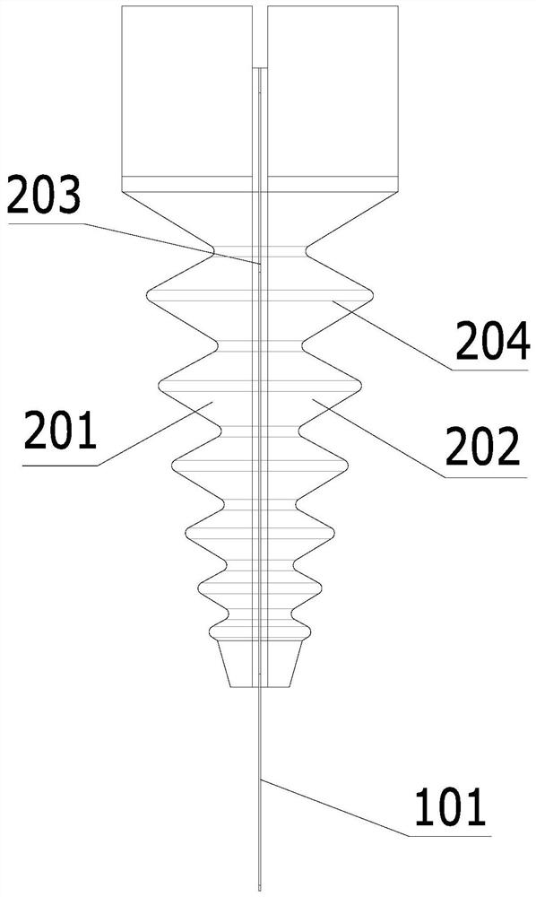
[0057] like Figure 1~4 As shown, a bionic fishtail propulsion mechanism includes: an elastic pendulum plate 101; a first cavity 201 and a second cavity 202 that are distributed on both sides of the elastic pendulum plate 101 and contain driving fluid; The hydraulic driving mechanism of the liquid pressure in the cavity 201 and the second cavity 202; a transmission surface 203 is provided between the elastic swing plate 101 and the first cavity 201 or the second cavity 202, and the first Driven by the pressure of the cavity 201 and the second cavity 202, the elastic pendulum plate performs a bending and rocking motion.

[0058] In this embodiment, the first cavity 201 and the second cavity 202 are symmetrically arranged along the elastic swing plate 101 . Adopting this technical solution is more conducive to realizing more precise control. The first cavity and the second...


PUM


Abstract

The invention discloses a bionic fishtail propelling mechanism. The mechanism comprises an elastic swing plate, a first cavity, a second cavity, a hydraulic driving mechanism and a transmission surface, wherein the first cavity and the second cavity are distributed on the two sides of the elastic swing plate and contain a driving liquid; the hydraulic driving mechanism is used for controlling thepressure of liquids in the first cavity and the second cavity; and the transmission surface is arranged between the elastic swing plate and the first cavity or the second cavity, and the elastic swingplate is driven by the pressure of the first cavity and the pressure of the second cavity to do bending swing motion. According to the bionic fishtail propelling mechanism, the elastic swing plate, the first cavity and the second cavity are introduced, the first cavity and the second cavity are located on the two sides of the elastic swing plate, stress control over the middle elastic swing plateis achieved through the two cavities, then a swing direction and a swing frequency of the swing plate are controlled, finally, the bionic fishtail propelling mechanism is controlled, control is moreflexible, and control precision is higher.

Description

technical field [0001] The invention relates to a propulsion mechanism, in particular to a high-efficiency bionic fishtail propulsion mechanism. Background technique [0002] Due to its flexible control and high driving efficiency, the bionic fishtail swing driving mechanism is more and more widely used in the field of mechanical driving. At present, the bionic fishtail swing driving mechanism is generally divided into: 1. The bionic fishtail driving mechanism driven by a mechanical structure. 2. Bionic fishtail drive mechanism through new smart materials. 3. Bionic fishtail drive mechanism driven by wire traction. 4. Bionic fishtail drive mechanism driven by hydraulic means. [0003] The existing bionic fishtail swing drive mechanisms driven by mechanical structures generally have complex structures, large volumes, and high failure rates. The existing bionic fishtail drive mechanism using new smart materials has different problems for different smart materials: it is di...

Claims


Application Information

Patent Timeline
IPC IPC(8): B63H1/36
CPCB63H1/36
Inventor 夏庆超励宏杨灿军张晟
Owner ZHEJIANG UNIV
Features
  • R&D
  • Intellectual Property
  • Life Sciences
  • Materials
  • Tech Scout
  • Unparalleled Data Quality
  • Higher Quality Content
  • 60% Fewer Hallucinations
Learn More