Rotary core cutting process for high-permeability or fractured formation

A high-permeability and technological technology, which is used in the extraction of undisturbed core devices, wellbore/well components, measurement, etc., can solve the problems of sidetracking, sticking failures, and easy drilling tool failures, so as to avoid jamming. Drilling accidents, the effect of reducing working torque and pulling force

Active Publication Date: 2020-11-20
BC P INC CHINA NAT PETROLEUM CORP +1
View PDF5 Cites 0 Cited by
  • Summary
  • Abstract
  • Description
  • Claims
  • Application Information

AI Technical Summary

Problems solved by technology

During drilling and coring operations, when the coring footage is completed or abnormality occurs in the middle, the drilling tool needs to be lifted to cut off the core at the bottom of the hole, and the drilling operation is carried out. A long segment of virtual thick mud cake will be formed. At this time, the conventional coring process is used to lift the drill tool to cut the core. Affected by the structure of the coring bit, there is a step at the top of each blade of the drill bit. The accumulation at the step (drilling fluid is mainly returned from the flow channel between the two blades), as the height of the drilling tool increases, the accumulated mud cake increases and is squeezed with the well wall to gradually form a slim hole, causing core cutting. When the drilling tool is blocked, the thicker the mud cake on the well wall, the more the drilling tool is raised, and the more serious the jam is. Due to the limited lifting, it is impossible to cut the core. When a fault occurs, the drilling tool, coring tool and core bit in the well are subjected to extremely high tension and torque, which is prone to drilling tool failure, and the core data cannot be analyzed in time. Manpower and financial resources, resulting in extended drilling cycle and increased costs

Method used


Image

  • Rotary core cutting process for high-permeability or fractured formation
  • Rotary core cutting process for high-permeability or fractured formation
  • Rotary core cutting process for high-permeability or fractured formation

Examples


Embodiment Construction

[0026] Hereinafter, the rotary core-cutting process for highly permeable or fractured formations of the present invention will be described in detail with reference to the accompanying drawings and exemplary embodiments.

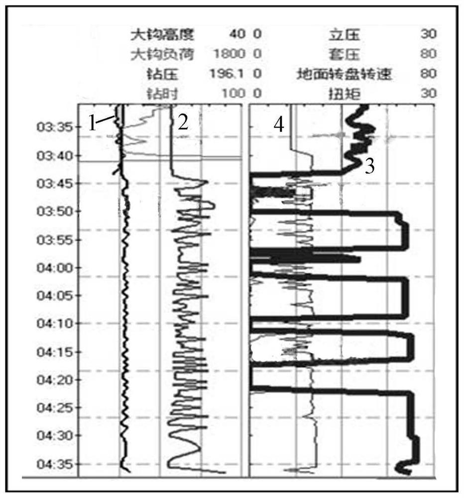
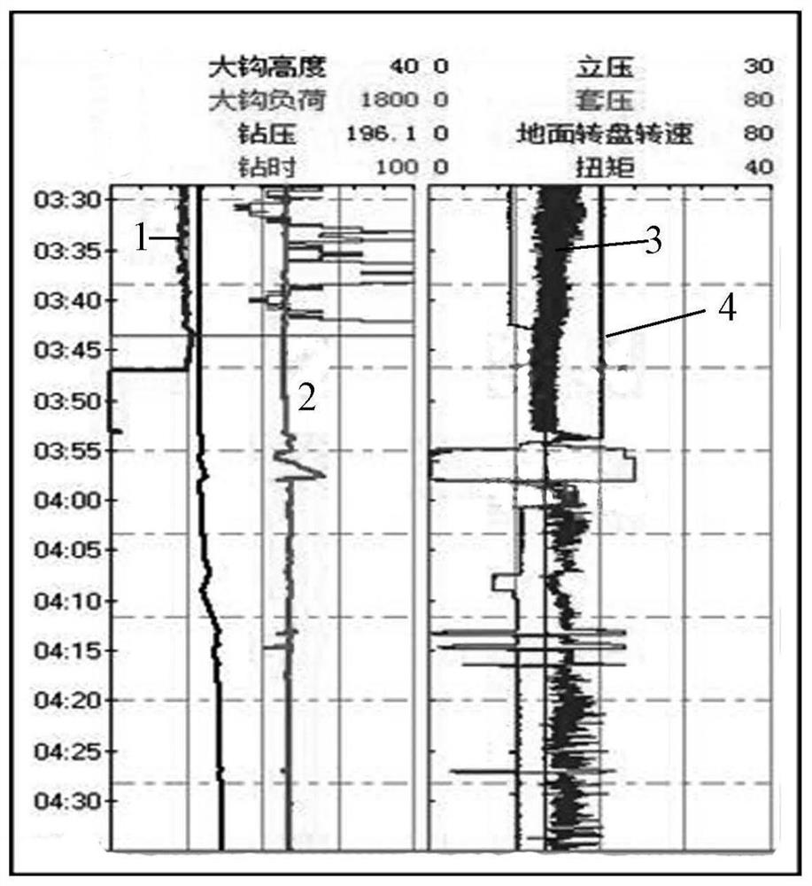
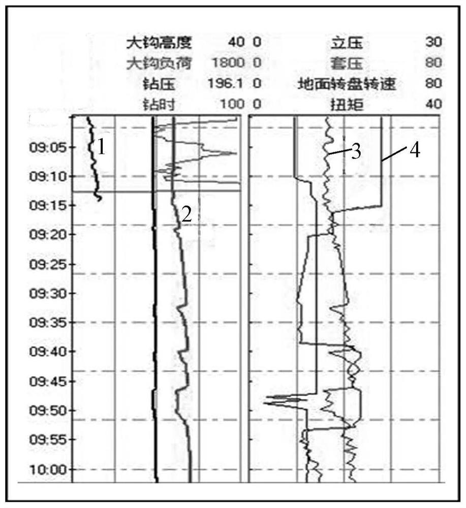
[0027] In an exemplary embodiment of the present invention, the rotary core-cutting process may include: coring in high-permeability or fractured formations, increasing the displacement cycle before the end of coring, non-stop top drive or rotary table before core-cutting, and not Stop the pump, lift the drilling tool intermittently, and use the core bit to rotate and repair the well wall to provide a safe passage for the core bit to go up to reduce the chance of jamming, and at the same time use the pulling force gradually generated by the intermittent lifting tool to cut the core.

[0028] Among them, the rotary core cutting process cannot continuously lift the drilling tool, and the height of the drilling tool for the first lifting should be determined acc...


PUM


Abstract

The invention provides a rotary core cutting process for high-permeability or fractured formation. The rotary core cutting process comprises the following steps: increasing displacement cycle of a pump after coring and drilling are accomplished, and not stopping a top drive or a rotary disc; not stopping the pump, discontinuously upwards lifting a drilling tool, cutting a rock core by pull force gradually generated by discontinuously upwards lifting the drilling tool, rotating and finishing a well wall by a coring drill bit, and providing a safety channel for the coring drill bit; after rock core cutting, reducing rotation speed of the top drive or the rotary disc, and continuously upwards lifting the drilling tool discontinuously until lifting the drilling tool to a safety well section. The rotary core cutting process has the beneficial effects that: the rotary core cutting process is suitable for complex well section coring, can greatly reduce working torque and tensile force borne on the drilling tool, the coring tool and the coring drill bit, can avoid a complex condition that normal drill lifting cannot be achieved as a result of frequent blocking during core cutting, can timely drill the core, analyzes data, and avoids the occurrence of a drill blocking accident.

Description

technical field [0001] The invention relates to the field of oil drilling, in particular to a rotary core-cutting process for high-permeability or fractured formations. Background technique [0002] The conventional coring process that has been used for many years is to stop the top drive or turntable before the end of each coring, and keep pumping up the drilling tool to generate a certain pulling force and act on the core claws at the lower end of the core inner cylinder, forcing the core claws to go down and Shrinks inside, jams and cuts off the core. The purpose of stopping the top drive or the turntable before cutting the core is to prevent the core from being thrown off due to the rotation of the drilling tool. This process has been used for decades, and it can fully meet the coring operations in normal downhole operations. [0003] As the country intensifies efforts to develop natural gas, the deployment of conventional and unconventional gas wells has increased yea...

Claims


Application Information

Patent Timeline
Patent Type & Authority Applications(China)
IPC IPC(8): E21B25/00E21B49/00E21B47/00
CPCE21B25/00E21B49/00E21B47/00
Inventor 段绪林卓云熊鸿照陈锦泉杨勇张运迪古光平张杰胡诚
Owner BC P INC CHINA NAT PETROLEUM CORP
Why Eureka
Try Eureka