Angle calibration method of absolute magnetic encoder based on vernier code channel

A technology of magnetic encoder and calibration method, which is applied in the direction of instruments, using electric/magnetic devices to transmit sensing components, etc., can solve problems such as mechanical installation errors and inability to obtain accurate absolute position information, and achieve easy implementation and simplified calibration process and calibration cost effects

Pending Publication Date: 2020-11-20
HARBIN INST OF TECH
View PDF7 Cites 0 Cited by
  • Summary
  • Abstract
  • Description
  • Claims
  • Application Information

AI Technical Summary

Problems solved by technology

[0003] The purpose of the present invention is to solve the problem that the absolute magnetic encoder cannot obtain accurate absolute position information due to the code track processi

Method used


Image

  • Angle calibration method of absolute magnetic encoder based on vernier code channel
  • Angle calibration method of absolute magnetic encoder based on vernier code channel
  • Angle calibration method of absolute magnetic encoder based on vernier code channel

Examples


specific Embodiment approach 1

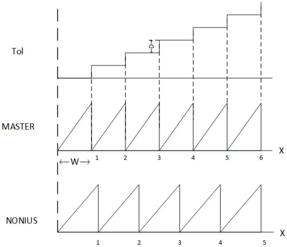
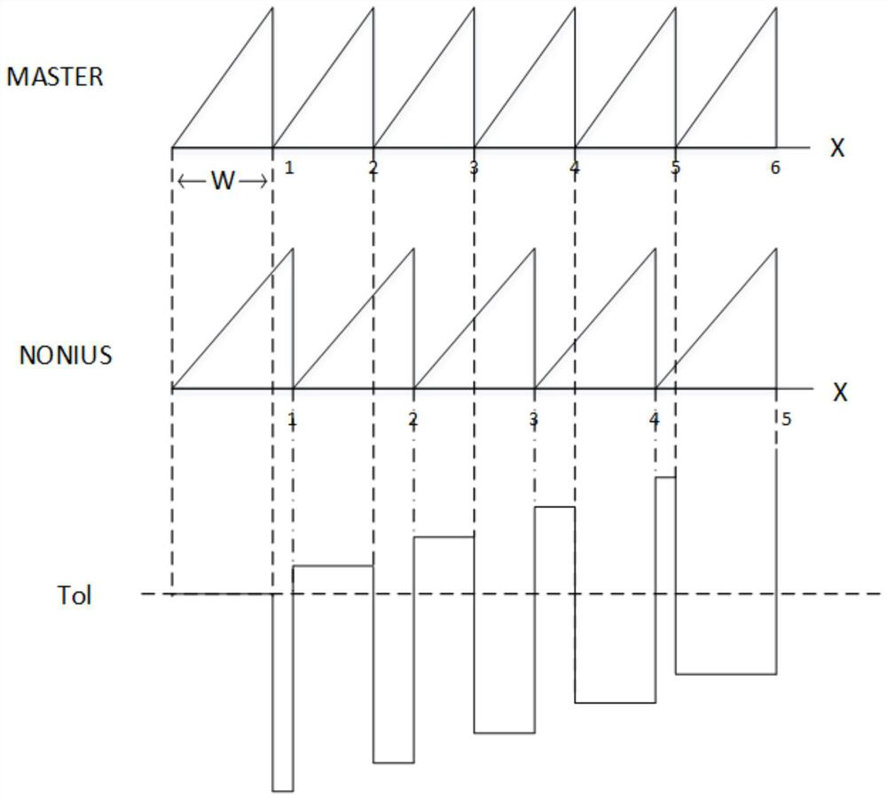
[0017] Specific implementation mode one: combine Figure 4 This embodiment will be described. The angle calibration method of the absolute magnetic encoder based on the vernier code track described in this embodiment, the method is specifically implemented through the following steps:

[0018] Step 1: Obtain the original data of the main code track and the vernier code track of the sensitive chip;

[0019] Step 2: Intercept the original data obtained in Step 1 to obtain data within a complete circle;

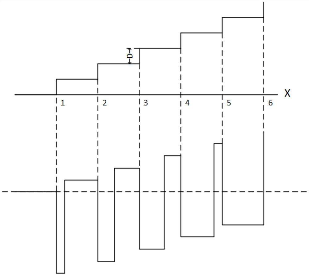
[0020] Step 3: Calculate the deviation value of each intermediate variable used to solve the absolute position according to the obtained data in the complete circle;

[0021] Step 4: Use the deviation value calculated in Step 3 to obtain calibration values ​​for calibrating each intermediate variable;

[0022] Step five: use the calibration values ​​obtained in step four to calibrate each intermediate variable to obtain calibrated intermediate variables; obtain absolute posit...

specific Embodiment approach 2

[0023] Specific implementation mode two: the difference between this implementation mode and specific implementation mode one is: the specific process of the step one is:

[0024] When the joint rotates in one direction, the original data p is collected according to the predetermined sampling period j , j=0,1,2,...,k-1,p j Represents the jth raw data collected, and k represents the number of raw data collected by the absolute magnetic encoder;

[0025] According to the collected original data, calculate the original data m of the main scale j and vernier raw data n j .

[0026] In this embodiment, the sampling period is determined according to the rotation speed of the joint (magnetic sensor) and the calibration time, so as to ensure that the position information of a complete circle and a certain number of sampling points are obtained during the entire calibration process (2000 sampling points / circle during the test).

[0027] The collected raw data is spliced ​​from the ...

specific Embodiment approach 3

[0029] Specific implementation mode three: the difference between this implementation mode and specific implementation mode two is: the specific process of said step two is:

[0030] Raw data of main scale m j and vernier raw data n j Form the original data sequence (m j ,n j ), j=0,1,2,...,k-1, perform cursor calculation on the original data sequence, and obtain the uncalibrated position sequence pos_raw j , j=0,1,2,...,k-1;

[0031] Intercept the subsequence pos with an angle value in the range of 0 degrees to 360 degrees from the uncalibrated position sequence j′ , j′=j 0 ,j 0 +1,...,j 1 , j 0 is the subscript of the first position value of 0 degree in the intercepted circle, j 1 is the subscript whose last position is 360 degrees, then the intercepted subsequence pos j′ The corresponding original data subsequence is (m j′ ,n j′ ), remark the subscript of the intercepted subsequence as j′=0,1,2,…,k 1 -1,k 1 = j 1 –j 0 +1,k 1 is the number of elements in the...


PUM


Abstract

The invention discloses an angle calibration method of an absolute magnetic encoder based on a vernier code channel, and belongs to the technical field of absolute position sensors. According to the invention, the problem that accurate absolute position information cannot be obtained due to code channel processing and mechanical installation errors of a coded disc and a sensitive chip of an absolute magnetic encoder is solved. When the absolute magnetic encoder is normally installed and used, original data used for calibration can be obtained only by rotating the absolute magnetic encoder formore than one circle in the same direction, and then accurate absolute position information can be obtained through the information calibration process of the main code channel and the vernier code channel output by the sensitive chip. According to the method, a special calibration platform is not needed, the calibration process and calibration cost of the absolute magnetic encoder can be simplified, and the calibration method has the advantage of being easy to implement. The angle calibration method can be applied to angle calibration of the absolute magnetic encoder.

Description

technical field [0001] The invention belongs to the technical field of absolute position sensors, and in particular relates to an angle calibration method of an absolute magnetic encoder based on a vernier code track. Background technique [0002] The position sensor is the basic component of the robot joint servo drive system. Commonly used feedback joints and motor position sensors can be mainly divided into two types: absolute and incremental. Absolute output the absolute position information within one or more turns, and the position information will not be lost when the power is turned on again; the position change pulse is output incrementally, and the current position information will be lost when the power is turned on again. According to the working principle, it can be divided into photoelectric encoder and magnetic encoder. The photoelectric encoder has the characteristics of high resolution, small speed fluctuation and high positioning accuracy; the magnetic enc...

Claims


Application Information

Patent Timeline
IPC IPC(8): G01D18/00G01D5/14
CPCG01D18/00G01D5/14
Inventor 倪风雷林鹏飞刘宏蒋再男金明河
Owner HARBIN INST OF TECH
Why Eureka
Try Eureka