
Access control machine based on face recognition

A face recognition and access control machine technology, applied in the field of face recognition-based access control machines, can solve the problems of reduced recognition effect, troublesome use, unfavorable users, etc., and achieve the effect of improving the degree of automation and reducing difficulty

Inactive Publication Date: 2020-11-20
广州云弈科技有限公司
View PDF0 Cites 4 Cited by
  • Summary
  • Abstract
  • Description
  • Claims
  • Application Information

AI Technical Summary

Problems solved by technology

[0003] At present, some access control devices with face recognition on the market are usually fixed on the wall during installation. When performing face recognition, users need to press the button of the access control device to turn on the access control motor, and put their face close to the access control device that comes with it. The face recognition camera requires a certain amount of time to operate, and it is troublesome to use. In addition, since the access control machine is fixed at a certain height, due to the different heights of users, the user needs to adjust his height according to the position of the face recognition camera of the access control machine. It is necessary for the user to maintain this height for a period of time for facial recognition. It is difficult to identify users with a large difference in height from the access control machine, which is not conducive to the use of users with a large difference in height. The recognition camera is usually exposed in the air. After the access control machine is used for a long time, it is easy to cause dust on the surface of the face recognition camera, which reduces the recognition effect and affects the normal use of the access control machine. Therefore, we propose a face recognition based access control machine

Method used


Image

  • Access control machine based on face recognition
  • Access control machine based on face recognition
  • Access control machine based on face recognition

Examples


Embodiment Construction

[0037] The following will clearly and completely describe the technical solutions in the embodiments of the present invention with reference to the accompanying drawings in the embodiments of the present invention. Obviously, the described embodiments are only some, not all, embodiments of the present invention.

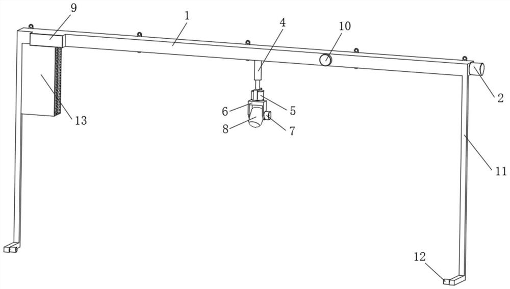
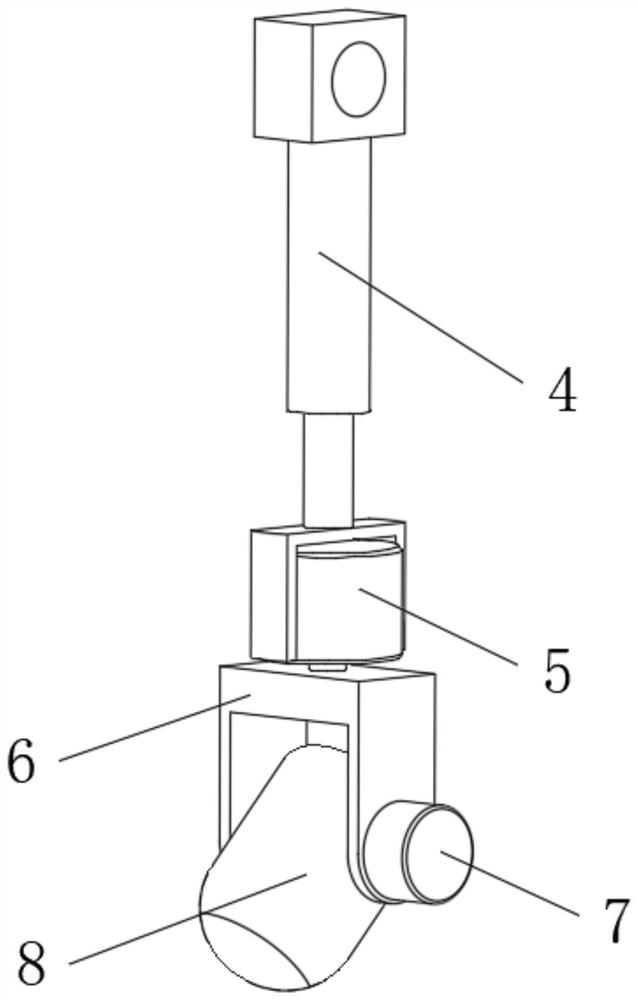
[0038] see Figure 1 to Figure 7 , the present invention provides a technical solution: an access control machine based on face recognition, including a fixed beam 1, a control terminal, a first servo motor 2 is fixedly installed on the right side of the fixed beam 1, and the output of the first servo motor 2 The shaft is fixed with a drive screw 3 inside the fixed crossbeam 1, and the external thread of the drive screw 3 is sleeved with an electric telescopic rod 4, and the bottom end of the electric telescopic rod 4 is fixedly equipped with a second servo motor 5, the second A card frame 6 is fixedly installed on the output shaft of the servo motor 5, and a face re...


PUM


Abstract

The invention discloses an access control machine based on face recognition, and relates to the technical field of access control machines, the access control machine based on face recognition comprises a fixed cross beam and a control terminal, a first servo motor is fixedly installed on the right side of the fixed cross beam, an output shaft of the first servo motor is fixedly sleeved with a driving lead screw located in the fixed cross beam, and the outer portion of the driving lead screw is sleeved with an electric telescopic rod in a threaded mode. In the access control machine based on face recognition, the infrared induction range finders on the left side and the right side are used for detection; when the infrared induction range finder detects a user, the infrared induction rangefinder sends a signal to the first-level controller, the first-level controller controls the first servo motor to drive the driving lead screw to rotate, and therefore the electric telescopic rod andthe face recognition camera are driven to move, face recognition is conducted on a user, automatic detection on the user is achieved, and the automation degree is improved.

Description

technical field [0001] The invention relates to the technical field of access control devices, in particular to an access control device based on face recognition. Background technique [0002] The access control machine is the core control device of the access control system. It uses large-capacity FLASH as the storage carrier. It has reliable data storage, and the data will not be lost when the power is off. It integrates management and automatic control. Realize the automatic management of access control, the data can also be used for attendance, realize the double function of access control and attendance, and can be seamlessly connected with the card system at the same time. It is widely used in access control, attendance management, security alarm, parking lot control, elevator control, building automatic control, etc. of intelligent buildings or intelligent communities. It can also be linked with other systems and other control functions. According to the communicatio...

Claims


Application Information

Patent Timeline
Patent Type & Authority Applications(China)
IPC IPC(8): G07C9/37G07C9/38G06K9/00G01S17/06G01S17/04G01C3/00G05D3/20B08B1/02B08B13/00B08B1/20
CPCG07C9/37G07C9/38G01S17/04G01S17/06G01C3/00G05D3/20B08B13/00G06V40/173G06V40/166B08B1/143B08B1/20
Inventor 周锦颜
Owner 广州云弈科技有限公司
Learn More